3022474 - 2710A drive shafts and joints
CONSTRUCTION FEATURES
The driveshafts are made from high resistance steel and have splined ends for matching with the constant velocity joints on the wheel side and the sliding joints on the gearbox side.The sliding joints are similar to the constant velocity joints, but have less articulation capacity.There is a balancing mass on the right driveshaft which damps vibrations.An intermediate shaft is fitted in order to be able to keep the length of the left and right driveshafts on the left side at the differential output the same. To prevent vibrations, depending on the version, the intermediate shaft is supported by a housing in the oil sump casting or by a support fixed to the cylinder block/crankcase.
CONSTANT VELOCITY JOINTS
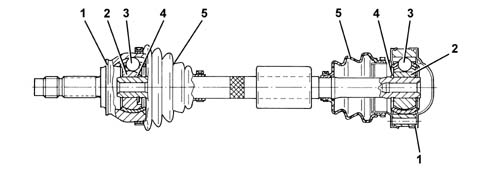
The constant velocity and sliding joints consists of:
- driven outer ring (1);
- an inner driving ring (2) fitted on the driveshaft;
- a transmission ball (3);
- a circlip (4);
- a protective boot (5).