3022487 - 3350A anti - spin regulation devices
SPECIFCATIONS
GENERAL VIEW
Specifications
Function
This system carries out all the normal anti-lock and brake distribution functions of the ABS 5.7 with EBD and also ensures the following:
- Acceleration Slip Regulation (A.S.R.)
- engine braking torque regulation (M.S.R.)
- differential lock via action on the brakes (T.C.)
Components
Structure
The system consists of:
- an electronic control unit built into the hydraulic control unit
- a hydraulic control unit which modulates the braking pressure acting on the brakes by means of twelve solenoids regardless of the driver's actions
- four ACTIVE sensors
- special wiring.
OPERATION
Operating principle
Introduction
The system processes the signals coming from the active sensors, the brake light switch and the button for switching the A.S.R. function on/off.It continually compares the speed of wheels on the same side of the car (Front right with Rear right - Front left with Rear left) and causes the ASR to cut in when a speed difference in excess of 2-6 km/h (cut-in threshold) is detected between wheels on the same side. The control unit turns on the MSR function when it detects an excessive difference between the front and rear axles because the front wheels tend to slow down too much compared to the rear wheels.The ABS/ASR control unit communicates continuously with the engine control unit via the C-CAN line.The ASR function is active under all car speed conditions. Braking action is cut out after 80 km/h.
Operating strategy
Drive wheel slippage
Intervention - intervention times in road conditions with good grip (asphalt)Torque reduction by the engine control unit by altering ignition advance - 6/100 s after the skid threshold is exceeded; Further torque reduction by reducing throttle opening (by the engine control unit with motorized throttle body) - after 15/100 s;Hydraulic system intervention (braking force on drive wheel) - after 2/10 s.Operation under conditions of poor gripThe system is able to detect this situation by comparing drive wheel acceleration with torque transmitted by the engine (engine load via engine control unit).The system performs in the same way as when both drive wheels are in road conditions with good grip (asphalt) and the cut in thresholds are at the lower limit.Only one drive wheel slipping.
Intervention-intervention timesTorque reduction by the engine control unit by altering ignition advances - 6/100 s after the threshold is exceeded;Further torque reduction by reducing throttle opening (by the engine control unit with motorized throttle body) - after 15/100 s.Effect on hydraulic system, braking action is exerted on the slipping wheel to give the differential a resistive force on the side with poor grip (T.C.)This resistive force allows the differential to transmit an equal torque with good grip.One wheel slipping on a bend with good grip (asphalt).The system detects the presence of a bend from the rear wheel speed (drawn).It implements the same intervention procedures described for when only one drive wheel is slipping; the cut-in thresholds are increased to the upper limit. The torque reduction is applied gradually.One wheel slipping on a bend with poor grip (snow or ice).It implements the same intervention procedures described for when only one drive wheel is slipping; the cut-in thresholds are increased to the lower limit. The torque reduction is accentuated (to ensure good car lateral containment).| Under A.S.R. operating conditions, when the control unit simultaneously receives a signal from the brake light switch, the system ceases to act on the brakes. The torque reduction part remains active. |
| With the brake lights switch activated, but with maximum braking pressure (e.g. tip of heel, defective switch, etc.), if the system detects a speed difference between the front and rear wheels which implies the operation of the A.S.R., only torque reduction is implemented. Brake intervention is excluded. |
Modulating braking torque with engine decelerating
Car instability during deceleration with poor gripThe system recognises the condition from engine load, front and rear wheel speed and brake pedal sensor. In this case, drive torque is increased when the engine control unit cuts in to open the motorised throttle. This overcomes the natural instability of the car due to the engine braking torque with poor grip.Cutting out the asr/mrs system
The ABS and EBD functions remain active if the system is cut out using a button on the panel, as it advisable if the cars are on certain surfaces (deep snow, deep mud, deep sand or gravel), or with chains on the drive wheels.Cut-in thresholds
Cut-in threshold differences, from 2 to 6 km/h, depend upon environmental factors. Some conditions are described in the operating strategies. Others are:
- high acceleration, thresholds high.
- car speed (see graph), tyre type (normal or winter). with winter type and good grip, high level threshold, with winter tyres and poor grip threshold low. The system is able to detect this situation by comparing drive wheel acceleration with torque transmitted by the engine (engine load via engine control unit).
| The A.S.R. function is activated at all vehicle speeds; braking action is, however, excluded above 80 km/h. |

Asr/msr system failure
If the ABS system is faulty, the ASR system is also disabled. The ASR system is cut out with the following faults:
- Engine C-CAN message errors
- C-CAN bus error
The ASR warning light strategy is as follows:
- with the A.S.R. on, the warning light in the dashboard is off and the LED on the button is off;
- with the A.S.R. operating, the warning light on the dashboard is intermittent and the LED on the button is off;
- with the ASR off, the warning light on the control panel is on, the warning light on the button is on and a message is displayed on the DOT matrix to indicate that the ASR is not activated
- when the ASR is faulty, the panel and button warning lights are on and an anomaly message is displayed on the DOT matrix.
Hydraulic system operation
The hydraulic unit on the version with A.S.R. has 4 additional solenoid valves.The inlet solenoid valve (normally closed), when activated, can receive the additional quantity of fluid required to increase the pressure and brake the wheel/s.The operating solenoid valve (normally open), when activated, allows the modulated pressure produced by the actual pump, necessary for the operation of the A.S.R., to be maintained in the pump-brake caliper circuit.When the ASR TC function is not on, the ECU:
- does not supply the (N.C.) inlet solenoid valve (2);
- does not supply the (N.A.) operating solenoid valve (3).

When the ASR/TC function is switched on, the electronic control unit:
- supplies the hydraulic pump (1)
- supplies the (N.C.) inlet solenoid valve (2)
- supplies the (N.A.) operating solenoid valve (3).

COMPONENT DESCRIPTION
Electrohydraulic unit
Composition
StructureThe hydraulic unit consists of a control unit and a hydraulic control unit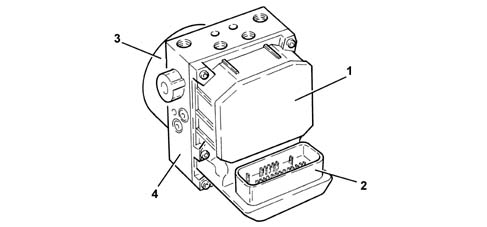
Electronic control
Specifications
FunctionThe electronic control unit is responsible for:
- downloading data from the wheel rpm sensors
- storing control parameters defined during the preparation of the vehicle
- storing the control software
- processes downloaded data
- controls the braking process
- detecting failures at the braking system components
- storing fault codes and activating ABS/EBD/ASR warning lights
- transmitting and receiving data via the diagnostic connector
- communicating with the engine control unit
- controlling the ASR/MSR process
- sending and receiving data via the C-CAN line

Hydraulic control unit
Specifications
FunctionResponsible for modulating the pressure of the fluid at the brake calipers via two solenoid valves with the following stages:
- brake fluid pressure increase
- brake fluid pressure maintenance
- brake fluid pressure discharge.
| ... DATA ERROR - CROPPED TEXT | Ошибка данных - Текст обрезан ... |
|---|