3022527 - 5550A stalk unit
INTRODUCTION
The diagram illustrates the controls for the steering column switch unit.
SPECIFICATIONS:
The diagram illustrates the steering column switch unit controls.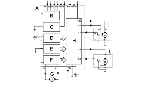
LIGHTS/DIRECTION INDICATORS CONTROLS OUTPUT INTERFACES (BETWEEN STEERING COLUMN SWITCH UNIT AND BODY COMPUTER)
BC1: Left direction controlBC2: Right direction controlBC3: Dipped headlamps controlBC4: Main beam headlamps controlBC6: Side lights controlTR: Trip computer controlWASH/WIPE INPUT CONTROLS INTERFACES
TC3: Windscreen wiper zeroing cam: this cam is a switch fitted on the motor which is normally closed when the wiper is in the rest position (windscreen wiper blades downwards and still).TL2: Rearscreen wiper zeroing cam: this cam is a switched fitted to the motor which is normally open when the wiper is in the rest positino (rearscreen wiper blade downwards and still). All the above signals are the active earthed type.RM: Reverse gear engaged signal: the control provides an active signal at +15 when reverse gear is engaged. The same control supplies the reversing lights.TCI-TC2: windscreen wiper control outputs;TL1: rearscreen wiper control output;P1-P2: electric pump control outputs;BC5: headlamp washer go ahead to Body Computer. The electronic module supplies a positive comman.RAIN SENSOR INTERFACES
The rain sensor should be supplied when the right lever is in the AUTOMATIC position:
- RS2: Rain sensor supply circuit by output electronic module (wiper functions);
- RS1: Hardware interface between rain sensor and input electronic module.
COMPONENTS AND OPERATION
THE CASING
It is a part of the steering column switch unit containing the electrical circuits and the switching and automatic release mechanisms which return the left lever to the rest position once the steering wheel has been realigned. Attachment angle 80° ± 5° release angle 60° ± 5°.
ELECTRONIC MODULE
This is the electronic control unit which controls the wiping functions and is mechanically secured to the CASING to which it is electrically connected by means of special terminals.It controls the operation of:
- Windscreen wiper: Sstroke frequency for all trim levels;
- Rearscreen wiper: stroke frequency and power assistance in reverse gear;
- Windscreen washer function: 'Smart' washing for all versions;
- Rearscreen washer function:'Smart' washing for all versions;
- Rain sensor: Management of signal coming from sensor - de-luxe version
CLOCK SPRING
It has two functions:
- to transmit the rotation of the steering wheel to the automatic release mechanism inside the CASING.
- to transfer the electrical signal for the controls on the steering column (horn and other optional serves) and connect the AIR-BAG module.
MULTI-PURPOSE SWITCH OR LEFT LEVER
It includes the lighting and direction indicator controls.All the commands are activated via the lever or the ring nut at the end of the actual lever.
Main lights switch
This control is at the end of the lever and is activated by turning a special ring nut.There are 3 stable positions for the ring nut when it is rotated in an anti-clockwise direction:
- Pos. 1 = No circuit switched on
- Pos. 2 = Side lights
- Pos. 3 = Side lights + go ahead for dipped/main beam headlamps + rear fog lamp.
Dipped/main beam headlamps switch
The operation is achieved by moving the lever perpendicular to the steering column (in other words lever moved from the rest position towards the dashboard).The control has two STABLE type positions, intermediat positions are not permissible.It is only possible to switch the dipped / main beam headlamps with the main lights switch (A) in position 3.Control for flasher - main beam
This operated by pulling the lever from the rest position towards the centre of the steering wheel, the action is UNSTABLE as a result of which when the lever is released it returns to the rest position.Direction indicators control
The direction indicators are operated by moving the lever on the steering wheel plane in two directions - clockwise and anti-clockwise.The automatic release device intervenes for each STABLE position of the direction indicators and has the function of returning the lever to the rest position after the steering wheel has been realigned.Fog lights control
The fog lights are activated by pressing a special button in the centre switch panel, thereby sending a signal to the body computer which, in turn, verifies and validates the activation.The body computer implements the following strategies: with the side lights/dipped headlamps on, the fog lights can be activated. When the main beam headlamps comes on as well, still with the fog lights on, the dipped headlamps are switched off automatically (to prevent the excessive build up of heat in the light cluster). When the main beam headlamps are flashed, the fog lights remain on.MULTI-PURPOSE SWITCH OR RIGHT LEVER
This includes the front and rear wiper controls. All the commands are activated via the lever or the ring nuts on the actual lever. There is also a button on the end of the lever which controls the trip computer functions.
Windscreen wiper operation (lever a)
The operation is achieved by moving the lever on the steering wheel, there are 5 different positions:Pos. 1 = No circuit switched on (STABLE): REST POSITION;Pos. 2 = Antipanic function (UNSTABLE): ANTI-CLOCKWISE DIRECTION;Pos. 3 = Intermittent / Automatic (STABLE): CLOCKWISE DIRECTION;Pos. 4 = 1ST SPEED continuous (STABLE): CLOCKWISE DIRECTION;Pos. 5 = 2ND SPEED continuous (STABLE): CLOCKWISE DIRECTION;Windscreen wiper intermittent adjustment / rain sensor sensitivity (ring nut a1)
This control is at the end of the lever and is operated by rotating a special ring nut in a clockwise direction in 4 stable positions corresponding to:
- BASIC TRIM LEVEL: from Pos. 1 to Pos. 4 = Increasing wiping frequency;
- DE-LUXE TRIM LEVEL: from Pos. 1 to Pos. 4 = Increasing rain sensor sensitivity;
ELECTRONIC MODULE (INCORPORATED IN STEERING COLUMN SWITCH UNIT)
This is the electronic control unit which controls the operation of the electric windscreen and rearscreen wiper motors and the smart washing functions; it is fixed mechanically to the CASING to which it is electrically connected by means of special terminals.In particular, it controls the operation of the:
- Windscreen wiper (stroke frequency for all trim levels);
- Rearscreen wiper (stroke frequency and power assistance in reverse gear);
- Windscreen washer function ('smart' washing for all versions);
- Rearscreen washer function ('smart' washing for all versions);
- Rain sensor (management of signal coming from sensor - de-luxe version)
| Compositino and operation in detail of windscreen wiper functions: also see subassembly 5050 windscreen washer and headlamp washer. |
REARSCREEN WASH/WIPE
This device has the task of cleaning the rearscreen effectively.It consists of a single motor with a 12 V supply which can operate at voltages between 9 and 16 V; it has a twin metallic type overload cut-out and does not have protection against radio interference.The wiper is constructed from a single wiper element made of a plastic arm and the linkage is internal. The jet is incorporated in the engine dust cover.
Rearscreen wiper control (ring nut c)
This control is on the lever and is activated by turning a special ring nut.The control has 2 STABLE positions and is turned in a clockwise direction:
- Pos. 1 = No circuit switched on;
- Pos. 2 = Rearscreen wiper operating intermittently;
Rearscreen washer operation (lever d)
It is operated by pushing the lever towards the dashboard, the operation is UNSTABLE as a result of which when the lever is released it returns to the rest position.The activation of the control involves the simultaneous operation of the rearscreen wiper with the 'smart washing' function (windscreen washer function).| Composition and operation of rearscreen wiper functions in detail: also see subassembly 5050 windscreen washer and headlamp washer. |
STEERING COLUMN SWITCH UNIT ELECTRONIC MODULE PIN-OUT
Rear view
| Connector A | ||
|---|---|---|
| PIN | Function | Nominal current [A] |
| 1 | Horn coil operation | 0.2 |
| 2 | Signal from rain sensor | 0.05 |
| 3 | Reverse signal for enabling rearscreen wiper | 0.05 |
| 4 | Rain sensor supply | |
| 5 | Headlamp washer go ahead | 0.05 |
| 6 | Windscreen wiper cam signal | 0.07 |
| 7 | Power earth | 2.5 - 3.5 |
| 8 | Second windscreen wiper speed | 1.7 - 4.0 |
| 9 | Windscreen wiper first speed/intermittent | 1.1 - 2.9 |
| 10 | Two-way pump (rearscreen washer positive) | 2.5 - 3.5 |
| 11. | INT/A for windscreen wiper / pump | 6.5 |
| 12. | Two-way pump (windscreen washer positive) | 2.5 - 3.5 |
| Connector B | ||
|---|---|---|
| PIN | Function | Nominal current [A] |
| 1 | Right direction indicator / parking control | 0.05 |
| 2 | Main beam headlamps / flasher control | 0.05 |
| 3 | Dipped headlamps control | 0.05 |
| 4 | Preparation for rear fog lamp go ahead | 0.2 |
| 5 | Earth for side lights control | 0.05 |
| 6 | Side lights control to Body Computer | 0.05 |
| Connector C |
|---|
| ... DATA ERROR - CROPPED TEXT | Ошибка данных - Текст обрезан ... |
|---|