3022528 - 5550B horns
INTRODUCTION
The diagram below shows a view of the assembly.
COMPOSITION
View of horn assembly
OPERATION
The pressure exerted on the centre of the steering wheel causes the compressino of one of the three springs, near the bolts fixing the Air Bag module (see Subassembly 5580C) which closes the circuit to earth.View of horn control circuit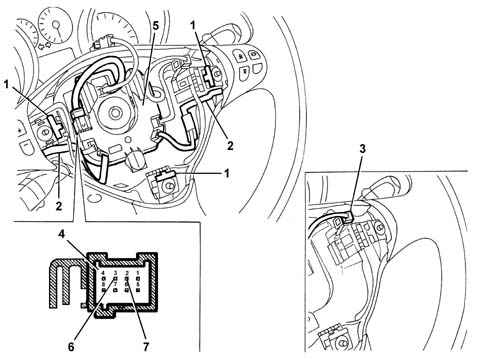
CLOCK SPRING
On versions without radio controls on the steering, on the side the clock spring is fixed to the steering column switch unit it has two connection points, one for the horn signal and one for the connection to the Air Bag module whilst on versions with radio/telephone and Selespeed controls on the steering wheel the connection is achieved via a single twelve-way connector.View of connection points to electrical system:
| The connecting cables should be fitted in the appropriate housing, at the base of the housing, to prevent possible interference with the Air Bag module. |