3022530 - 5560B analogue control panel
SPECIFICATIONS
INTRODUCTION
The instrument panel on the 147 is fitted in the B-CAN network and takes the name NQS (instrument panel connector)The signals involving the systems in the C-CAN network are available to the NQS from the Body Computer connector via an interface known as a Gateway.The task of the NQS is to the display the vehicle operating parameters and inform the user of possible failures in the electronic on board systems.There are two basic versions of N.Q.S. the LOW LINE type N.Q.S. and the HIGH LINE type N.Q.S.The LOW LINE version has two LCDs in TN technologyThe HIGH LINE version has a TN technology LCD and a DSTN technology DOT displayThe instrument panels also come with either a grey background or a black background to match the interior fittings| the GTA model has the HIGH LINE version with several variants indicated below. |


PIN OUT
The diagram below illustrates the PIN OUT.
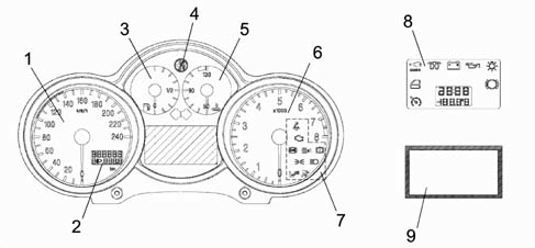
INDICATOR PANELS
The diagram below shows the indicator panels.
Table of warning lights and location in nqs
| Name | Colour | Symbol (see diagram) | Display HIGHLINE | Display LOWLINE | Display in position |
|---|---|---|---|---|---|
| Oil pressure | red | 1 | symbol + message in matrix display | LED | Centre panel |
| Engine coolant temperature | red | 2 | LED and symbol + messagey in matrix display | LED | Engine coolant temperature panel |
| Handbrake applied | red | 3 | LED and symbol + messagey in matrix display | LED | Rev counter panel |
| Brake circuit failure:- insufficient brake fluid- EBD failure (with ABS warning light on) | red | 4 | LED and symbol + messagey in matrix display | ||
| Brake pad wear | red | 5 | symbol + message in matrix display | LED | Centre panel |
| Alternator failure | red | 6 | symbol + message in matrix display | LED | centre panel |
| Fuel reserve | amber | 7 | LED | LED | fuel level panel |
| Outside lights failure | amber | 8 | message in matrix display | LED | centre panel |
| ABS | amber | 9 | LED and symbol + messagey in matrix display | LED | rev counter panel |
| AIR-BAG | red | 10 | LED | LED | rev counter panel |
| Passenger air bag disabled | amber | 11 | LED | LED | rev counter panel |
| Engine management failure (JTD only) | red | 12 | LED and symbol + messagey in matrix display | LED | rev counter panel |
| EOBD (engine management failure) - petrol versions | amber | 12 | LED and symbol + messagey in matrix display | LED | rev counter panel |
| Right direction indicator | green | 13 | LED | LED | centre panel |
| Left direction indicator | green | 14 | LED | LED | centre panel |
| Side lights on | green | 15 | LED | LED | rev counter panel |
| Main beam headlamps | blue | 16 | LED | LED | rev counter panel |
| Door/s open | red | 17 | Symbol + message in matrix display | LED | centre panel |
| Immobilizer (CODE) | amber | 18 | Symbol + message in matrix display | LED | centre panel |
| Seat belt | red | 19 | LED | LED | centre panel |
| TC / ASR | amber | 20 | LED and symbol + messagey in matrix display | LED | rev counter panel |
| VDC | amber | 21 | LED and symbol + messagey in matrix display | LED | rev counter panel |
| Inertia swith on | amber | 22 | symbol + message in matrix display | LCD (2): 'FPS on' | DOT matrix (HL) LCD (2) (LL) |
| Cruise Control | green | 23 | symbol + message in matrix display | LED | Centre panel |
| Ice danger signal | amber | 24 | symbol + message in matrix display | LCD (2) Outside temp. flashing | DOT matrix (HL) |
| Selespeed failure | red | 25 | symbol + message in matrix display | --- | DOT matrix (HL) |
| Info-telephone repetition: incoming call SMS | green | 26 | symbol + message in matrix display | --- | DOT matrix (HL) |
| Speed limit warning | red | 27 | symbol + message in matrix display | --- | DOT matrix (HL) |
| Speed limit warning for Arab market | red | 28 | message in matrix display | ---- | DOT matrix (HL) |
| Heater plugs | amber | 29 | symbol + message in matrix display | LED | Centre panel |
| Water in diesel filter | amber | 30 | symbol + message in matrix display | --- | DOT matrix (HL) |
| The symbols display appear in a 32 x 23 pixel window in the lower right part of the matrix; this part can be lit in 3 different colours (red, amber or green). |

Display information table
| LOW version | HIGH version | |
|---|---|---|
| DISPLAY (1) LCD TN | • milometer• headlamp alignment• engine oil level (JTD)• light adjustment | • milometer• headlamp alignment |
| DISPLAY (2) LCD TN | • clock• outside temperature• inertia switch indication• buzzer volume adjustment | Not present |
| DISPLAY (2) LCD DOT – DSTN | Faults (symbol + message)ClockDateOutside temperatureEngine oil temperature (GTA)Trip ComputerRadio Info/Telephone/NavigationSet up menuServiceEngine oil level (JTD)Light dimmerRobot gearbox info |
Fault diagnosis
The instrument panel can be diagnosed using the diagnostic equipment in the Network (Examiner or Examiner plus).The diagnostic socket is located in the EOBD, the dialogue line consists of the B-CAN line.The following operations can be carried out through diagnosis:
- Display of possible errors in the instrument panel
- Programming milometer mileage
- Setting mileage for SERVICE function (replacing instrument panel)
- Active diagnosis in order to check the operation of the instrument panel
| When the panel is replaced, the PROXI alignment must always be carried out (using the specific programme), if this is not done, the milometer will flash and the panel will not be fully operational. |
COMPOSITION
The N.Q.S. consists of:
- Instrument panel on suitable versions in front of the driver with B-CAN interface
| ... DATA ERROR - CROPPED TEXT | Ошибка данных - Текст обрезан ... |
|---|