3026087 - Introduction - PETROL INJECTION SYSTEM
BOSCH M7.3.1 EOBD injection system
VIEW OF ASSEMBLY1 - Electric fuel pump
2 - Relays
3 - Lambda sensors downstream of catalyzer
4- Lambda sensors upstream of pre-catalyzer
5 - Speedometer
6 - Rev counter
7 - Injection warning light
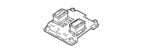
8 - Injection/ignition control unit
9 - Fuel vapour recirculation solenoid valve
10 - Throttle body integral with D.V.E.
11 - Climate control connector
12 - Diagnostic connector
13 - Alfa Romeo CODE connector
14 - Air flow meter with air temperature sensor
15 - Coolant temperature sensor
16 - City (Selespeed version only)
17 - Brake pedal dual switch
18 - Clutch pedal switch
19 - Accelerator pedal potentiometer
20 - Rpm sensor
21 - Knock sensor
22 - Ignition coils
23 - Timing sensor
24 - Variable valve timing
25 - Injectors
26 - Modular intake manifold solenoid valve (excluding 1.6 version)Construction features
Engine with 4 cylinders in line, twin spark
ignition, 16 valves, twin overhead camshaft, electro-hydraulic variable
valve timing (excluding 1.6 105 bhp version), counter-rotating balancer
shafts (2.0 version), motorised throttle body, equipped with Bosch
Motronic ME7.3.1 EOBD integrated electronic injection/ignition.General characteristics
The unit comprises the engine and
all the systems required for its operation:
- fuel supply system
- air supply system;
- engine cooling system
- exhaust system with two pre-catalyzers, connected to
the exhaust manifold, and one main catalyzer, positioned under the
bodyshell.
- fuel vapour recirculation system
The operation of these systems is optimized
by an electronic control system governed by a control unit.An understanding of the operating logic
of the control unit gives an overall picture of the entire GROUP
10 system.Operation of the injection/ignition system
The Bosch Motronic ME7.3.1 system
with a motorized butterfly belongs to the category of integrated
systems with:
- ignition
- sequential and phased electronic injection.
The control unit controls the air flow rate
at the rotation speed set through the electronic throttle.The control unit controls the moment of
ignition in order to keep the engine running smoothly as the ambient
parameters and loads applied vary.The control unit controls and manages the
injection so that the air/fuel ratio is always close to the stoichiometric
value to maximize the conversion efficiency of the catalyzers.The main operating principles of
the system are basically as follows:
- self-learning;
- system self-adaptation;
- autodiagnosis;
- recognition of the Alfa Romeo CODE (Immobilizer);
- control of cold starting;
- control of combustion - Lambda sensors;
- control of knock;
- control of mixture enrichment during acceleration;
- fuel cut-off with the accelerator pedal released;
- fuel vapour recovery;
- control of the maximum rpm;
- control of the fuel pump;
- connection to the climate control system
- recognition of cylinder position;
- control of the optimum injection time for each cylinder;
- adjustment of ignition advance values;
- management of the idle speed (also according to the
battery voltage);
- management of throttle opening laws (City mode - Selespeed
version only);
- control of the electric fans;
- connection with ABS control unit;
- connection with the gearbox control unit (Selespeed
version only);
- connection with the instrument panel;
- torque management;
- fuel system diagnosis;
- catalyzer diagnosis;
- misfire diagnosis; misfire detection
- Lambda sensors diagnosis.
Torque control strategy
The drive by wire systems represent vital
tools in satisfying legal requirements such as emissions and fuel
consumption in addition to improvements in the driveability of vehicles
with petrol engines (starting, heating, transition response, driving safety,
immobilizer, etc.).The torque for most common petrol engines
is mainly affected by the throttle valve which controls the mass
of air drawn in by the engine (according to the position of the
accelerator pedal) and therefore also the refilling of the cylinder.In addition to this there are also other
parameters which affect the variation of the engine torque: the
ignition angle, the air/fuel ratio (Lambda), the deactivation of
the injection in certain cylinders, likewise the control of the
increase in pressure in engines with turbochargers.Examples of other elements which affect
torque are: the EGR, the adjustment of the camshaft and the switching
of the intake manifold.Fuel injection system
The essential conditions that must
always be met in the preparation of the air-fuel mixture for the
correct operation of controlled-ignition engines are mainly:
- the 'metering' (air/fuel ratio) should constantly be
kept as close as possible to the stoichiometric ratio, so as to
ensure the maximum conversion capacity for the catalytic converter
(max. efficiency).
- the 'homogeneity' of the mixture, consisting of petrol,
diffused as finely and evenly as possible in the air.
The information processed by the
control unit for controlling optimum metering is received in the
form of electrical signals emitted by:
- air flow meter and air temperature sensor, for the exact
quantity of air drawn in
- rpm sensor which produces an alternating, single-phase
signal whose frequency indicates the engine rpm. This signal is
used by the control unit to detect misfire
- throttle potentiometer, to recognize the acceleration
conditions requested
- coolant temperature sensor located on the thermostat
- Lambda sensors to determine the oxygen content of the
exhaust gases and, through the downstream sensor, to diagnose the
efficiency of the catalyzers.
Ignition system
The ignition is the inductive discharge
type, (i.e. without a high tension distributor) with power modules
located in the fuel injection control unit.In the ignition system each coil supplies
the spark plugs for the appropriate cylinder.The advantages of this solution are:
- less electrical overload;
- guarantee of constant discharge at each spark plug.
Stored in the control unit, there is a map
containing the entire set of optimum ignition advance values (for
the cylinder at the power stroke) that the engine can adopt in relation
to the rpm and required engine load.The control unit corrects the advance
values mainly in accordance with:
- engine coolant temperature
- intake air temperature
- knock
- throttle valve position
The information which the control
unit processes to operate the ignition coils is received by means
of electrical signals emitted by the:
- air flow meter and air temperature sensor, for the exact
quantity of air drawn in
- rpm sensor, which generates an alternating single-phase
signal whose frequency indicates the engine rpm
- knock sensor (on the rear of the engine block between
the 2nd and 3rd cylinders) which recognizes which cylinder is knocking
and corrects its ignition advance
- throttle position potentiometer, to recognize minimum,
partial opening and full load conditions
- timing sensor.
OPERATING
Diagram of input/output info to/from control
unit1 - Electric fuel pump
2 - Air conditioner compressor
3 - Electric fan
4 - Lambda sensor downstream of catalyzer
5 - City (Selespeed version only)
6 - Quadrinary
7 - Brake pedal switch
8 - Timing sensor
9 - Speedometer
10 - Lambda sensors upstream of pre-catalyzers
11 - Coolant temperature sensor
12 - Knock sensor
13 - Rpm sensor
14 - Accelerator pedal potentiometer
15 - Air flow meter with air temperature sensor
16 - Battery
17 - Clutch pedal switch
18 - Throttle body integrated with D.V.E.
19 - CAN line (for communication with ABS/ASR and automatic transmission
control units Selespeed version only)
20 - Alfa Romeo CODE
21- Diagnostic socket
22 - Fuel vapour recirculation solenoid valve
23 - Ignition coils
24 - Injection warning light
25, Modular intake manifold solenoid valve (2.0 only)
26 - Rev counter
27 - Variable valve timing
28 - InjectorsOperating logics
Self-learning
The control unit implements the self-learning
mode in the following conditions:
- removing-refitting or replacement of the injection control
unit
- removing-refitting or replacement of the throttle body
integrated with D.V.E.
- removing-refitting or replacement of the rpm sensor/flywheel,
for recognizing misfire.
The values memorized by the control unit
are preserved if the battery is disconnected.System self-adaptation
The control unit has a self-adaption function
which recognizes changes in the engine which occur as a result of
bedding-in and ageing processes of both components and the engine
itself.These changes are stored in the form of
modifications to the basic mapping, and their purpose is to adapt
the operation of the system to the gradual alterations in the engine
and components compared with their characteristics when new.This self-adaptation function also makes
it possible to even out inevitable differences (due to production
tolerances) in any replaced components.From the exhaust gas analysis, the control
unit changes the basic mapping in relation to the original characteristics
of the new engine.The self-adaptation parameters are not cancelled
if the battery is disconnected.Self-diagnosis
The control unit autodiagnostic system controls
the correct operation of the system and signals any faults by means
of an (MIL) warning light in the instrument panel which has a standardized
European colour and ideogram. This warning light signals both engine
management faults and problems detected by the EOBD strategies.The (MIL) warning light operating
logic is as follows:
- with the ignition key in the ON position, the warning
light comes on and remains on until the engine has been started up.
The control unit's self-test system checks the signals coming from
the sensors, comparing them with the permitted limits:
Signalling of faults during engine
starting:
- the failure of the warning light to go out once the
engine has been started up means that there is an error memorized
in the control unit.
Fault indication during operation
- the warning light flashing indicates possible damage
to the catalyzer due to misfire.
- the warning light on constantly indicates the presence
of engine management errors or EOBD errors.
RECOVERYFrom time to time, the control unit defines
the type of recovery according to the components which are faulty.The recovery parameters are managed by those
components which are not faulty.Recognition of the alfa romeo code
When the NCM control unit receives the ignition
'ON' signal, it communicates with the Body Computer (Alfa Romeo
CODE function) to obtain starting enablement.Communication takes place via the dedicated
bidirectional serial diagnostic line which connects the two control
units.Control of cold starting
The following occurs during cold
starting:
- a natural weakening of the mixture because of the poor
evaporation of the fuel at low temperatures
- condensation of the fuel on the inner walls of the inlet
manifold
- increased viscosity of the lubricant oil.
The electronic control unit recognizes
this condition and corrects the fuel injection time in accordance
with:
- coolant temperature
- intake air temperature
- battery voltage
- engine rpm.
The ignition advance depends solely on the
engine rpm and the coolant temperature.Whilst the engine is warming up, the electronic
control unit operates the idle speed actuator, which determines
the quantity of air required to guarantee that the engine speed
is sustained.The rpm is made to decrease in proportion
to the increase in temperature of the engine until the optimum value
with the engine up to temperature is obtained.Check on combustion - lambda probe
In EOBD systems the Lambda sensors, which
are all the same type, are located upstream of the catalyzer and
downstream of the catalyzer. The upstream sensors carry out the
check on the mixture strength known as the 1st loop (upstream sensor closed
loop). The sensor downstream of the catalyzer is used for the catalyzer
diagnosis and for finely modulating the 1st loop control parameters.
With this in mind, the adjustment of the second loop is designed
to recover both production differences and those in the response
of the upstream sensors which may occur as a result of ageing and
pollution. This control is known as the 2nd loop (downstream sensor
closed loop).Check on variable valve timing and modular inlet
manifold
To optimize the quantity of air drawn
in by the engine, the control unit checks:
| ... DATA ERROR - CROPPED TEXT | Ошибка данных - Текст обрезан ... |
|---|