3026112 - Introduction - AIR CONDITIONING CASING AND COMPONENTS
SPECIFICATIONS:
INTRODUCTION
As a result of primary and secondary physiologial processes involving the activities of human beings, the air in the environment in which they live is altered with an increase in the rate of carbon dioxide, a decrease in the percentage of oxygen, the emission of aromatic substances (e.g. from smoking) and an increase in the concentration of pathogenic bacteria; this all makes a closed environment less healthy, especially if a small area is involved.One of the solutions for improving these conditions is the use of an air conditioning system.An efficient air conditioning system fitted in the vehicle should control the main environmental factors which determine the physiological conditions for the well-being of people, namely:
- the temperature;
- the humidity;
- the speed of the air;
- the purity of the air in the passenger compartment.
The variation in the temperature and the humidity of the air in the passenger compartment is achieved by the following two systems:
- manually operated climate control system, which is fitted as standard on the vehicle.
- automatically controlled temperature (twin zone) and ventilation climate control system, available as an option of vehicles with higher specification levels.
Coolant fluid
The fluids used in a refrigerating circuit as known as refrigerants. These are fluids which, in addition to having a LOW BOILING POINT at normal pressure, should also have:
- A LOW FREEZING POINT, to prevent solidification in even the harshest climates;
- A HIGH EVAPORATION TEMPERATURE (passage from a liquid state to a gaseous state);
- A LOW CRITICAL TEMPERATURE (maximum temperature above which it is no longer possible to liquify the gas, irrepsective of the pressure applied).
In addition, they should not be:
- EXPLOSIVE AND FLAMMABLE; these requirements are vital to avoid danger in the case of leaks inside the engine compartment;
- TOXIC OR NOXIOUS; in order not to create problems for people;
- OXIDIZING AND/OR CORROSIVE; in order not to destroy the system constituent materials;
- It should also be possible to mix them with the lubricants used in these sysetm to guarantee the perfect lubrication of all the system constituent components (compressor, expansion valve, pipes, connectors, etc.).
Fluids for refrigerant systems
This fluid is necessary for lubricating the gaskets, seals, washers and other moving parts of the compressor. A certain amount of fluid is carried along in the circuit with the refrigerant and helps to keep the expansion valve in optimum operating condition. Only specific fluids which do not produce foam should be used in air conditioning systems. These are highly refined mineral oils from which the impurities, such as wax, sulphur and water have been thoroughly removed. Engine oil should not, under any circumstances, be used in air conditioning systems.Always follow the compressor manufacturer's recommendations before introducing oil into the refrigerant system.Main air conditioning system components
The main components of the air conditioning system are illustrated in the diagram.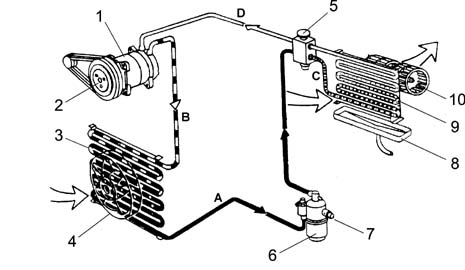
Refrigerant circuit (operation)
The aim of refrigerant equipment is to absorb heat from the atmosphere. In order to do this an air conditioner makes use of the behaviour of certain fluids (known as refrigerants) which are capable of cooling down (lowering their temperature) and changing state (from liquid to gas) when they are subjected to a substantial decrease in pressure and they expand. They are thereby able to absorb heat from the surrounding ambient. When their temperature increases, also increasing the pressure, they change state again (from gas to liquid) as they condense.The first problem is therefore to liquefy this gas, which can only be achieved by bringing it to a temperature below evaporation (or boiling) point which, as we have already said, is -26° C at atmospheric pressure for R134a.For this to be achieved at ambient temperature which, in our case, can be rather high (in the engine compartment), it is necessary to increase the evaporation point of the gas so that it remains liquid until the moment it is made to expand to produce the desired refrigerant effect.To increase the boiling point of the gas it is necessary to increase its pressure, at the same time decreasing its temperature.The system requires a certain amount of power in order to do this. This power, supplied by the compressor, is removed from the power produced by the engine.The operating principle of the refrigerant cycle stages in a vehicle's air conditioning system can be summarized as follows.The gaseous R134a refrigerant is drawn in by the compressor at a pressure of between 0.5 and 2 bar and by the end of the compression it reaches between 10 and 17 bar. At these pressures the boiling point reaches around 60 ° C.This fluid, heated by the compression stage to 80 - 100 ° C, still in a gaseous state in the condenser where, as a result of the cooling air flow (produced by the movement of the vehicle or the action of the fan) which passes through, reaches condensation point, changing to a liquid state at high pressure.The refrigerant then goes into a filter which has three functions: retaining impurities, absorbing the humidity contained in the circuit and working as a reserve reservoir for the actual refrigerant.The refrigerant then reaches the expansion valve where it is introduced into the evaporator where the pressure is around 1.5 atm. (1.52 bar). At this pressure the liquid-saturated vapour sysetm for the refrigerant is in equilibrium at a temperature of about -7 ° C. At the same time, the air which passes through the evaporator (through the action of the fan), being at a considerably higher temperature than the refrigerant fluid it contains, causes boiling and complete evaporation by giving off this heat. The air, on cooling down, deposits some of the humidity it contains on the evaporator fins in the form of droplets which collect in a tank and are discharged outside the vehicle.The air, which has been cooled and dehumidified, is sent to the inside of the vehicle. The refrigerant at the evaporator outlet is drawn in again by the compressor, starting a new cycle.Summary of the refrigerant fluid's route:
- 1) In the compressor - the fluid coming from the evaporator is in a gaseous state (temp. -5, -7° C, pressure 0.5 - 2 bar). Compression stage - the gaseous fluid is heated (temp. 80 -100 ° C, pressure 10 - 17 bar).
- 2) Condenser - Compression stage: the fluid gives off heat to the outside, cools down and becomes liquid again (temp. 40 - 60° C, pressure 10 - 17 bar).
- 3) Thermostatic expansion valve - Expansion stage - the fluid loses pressure (0.5 - 2 bar to reach even 3 bar) and becomes a mixture of gas + liquid; the temperature is low, typical of air conditioning.
- 4) Evaporator - Evaporation stage - the fluid becomes completely gaseous because the hot air driven by the fan finds itself at a higher temperature than the refrigerant fluid causing it to boil and evaporate completely, giving off heat. The temperature is low, that of the air conditioning (pressure 0.5 - 2 bar).
TWIN LEVEL AUTOMATICALLY CONTROLLED CLIMATE CONTROL SYSTEM
The automatic climate control is managed by a control unit which, thanks to an extremely sophisticated operating logic, is capable of controlling the temperature in two areas of the passenger compartment, heating or cooling the incoming air so that it reaches the desired temperature. It is also capable of demisting 60% of the windscreen surface and 20% of the side windows relatively quickly (in about 5 minutes) which improves safety.This performance is achieved thanks to the excellent software logic and the air distribution.Location of system components
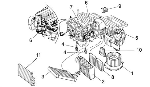
The diagram shows the location of the main components.
Interior air circulation diagram
The diagram illustrates the circulation of the air in the passenger compartment.
COMPONENT DESCRIPTIONS
CONVEYOR/DISTRIBUTOR UNIT
It consists of two modules which contain inside:
- the fan
- the evaporator
- the actuators controlling the upper mixture, distribution and recirculation flaps
- the heater radiator
- the lower mixed air temperature sensor.

The air introduced into the passenger compartment from the outside passes through a combined filter, i.e. consisting of two layers:
- the first 'particle' layer has the task of trapping the small particles of fine dust and pollen
- the second 'active charcoal' layer is designed to trap certain pollutant elements in the atmosphere.
CLIMATE CONTROL CONNECTOR NCL OR ELECTRONIC CONTROL UNIT
The diagram below illustrates the system controls.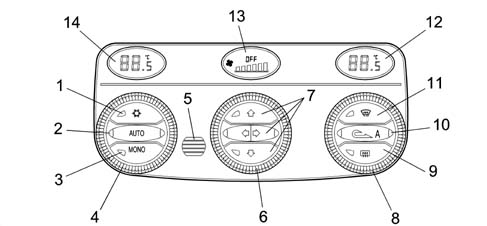
| ... DATA ERROR - CROPPED TEXT | Ошибка данных - Текст обрезан ... |
|---|
INTERIOR FAN
The motor which sends outside or recirculation towards the evaoprator battery is an electric motor with permanent magnets of the same type used for the condenser fan but with a different (lower) electric power. It is located inside the casing, near the evaporator; it receives a 12 V supply and is operated at different speeds by an electronic governor located nearby. The various operating speeds are necessary to activate the condensation of the refrigerant with a ventilation that would be imopssible to produce dynamically, especially with the vehicle stationary or in traffic.
ELECTRONIC GOVERNOR
The different fan rotation speeds are controlled by an electronic governor fixed to the actual duct. Using P.W.M. (pulse width modulation) signals, pin 8 of the (NCL) control unit, at the governor electronic system input, the voltage and consequently the supply current for the motor are controlled with a consequent control of the speed of the fan and the cubic metres/hour of the air.In addition, the governor processes a feedback signal with a frequency proportional to the rotation speed of the motor at pin 32 of the (NCL) control unit. It is used as a control signal for the rotation speed of the motor to diagnose increases in temperature due to current absorption or excessive mechanical resistance; in practice, any malfunctions.
POLLEN FILTER
It has been decided to fit a combined type air filter (PARTICLES+ ACTIVE CHARCOAL) for the passenger compartment on air conditioned vehicles to improve comfort. The former makes it possible to prevent the intake of pollen and pollutant particles into the passenger compartment; the latter reduces the tiresome sensation produced by unpleasant smelling substances due to dampness forming on the surfaces.
The main specifications of the filter element are:
- high filtering capacity: the filter retains more than 50% of particles with dimensions between 0.5 (1micron, above 80% between 1( 1.5 microns, around 98% with dimensions above 2 microns
- easy to replace.
CONTROL UNITS USED IN CLIMATE CONTROL SYSTEMS
The diagram shows the control units which may be used.
Winter pack 2 has the following sensors:
- a) misting sensor
- b) rain sensor
- c) pollution sensor (a.q.s.)
MANUALLY OPERATED CLIMATE CONTROL
Variants compared with the dual zone systemAir conditioner controls
The air conditioner control unit is located in the middle of the facia. The controls are located outside the housing.
The positions indicated by a white symbol correspond - in a clockwise direction - to:
- flow to front outlets only,
- flow to front and lower outlets,
- flow to lower outlets only,
- flow to lower outlets and windscreen,
- flow to windscreen only;
The last position, indicated in yellow, corresponds to the max. defrosting function. This automatically sets ideal conditions for rapidly demisting/defrosting the windscreen; i.e.:
- flow directed entirely to the windscreen;
- maximum air output
- as much warm air as possible taken into the mixture;
- air taken from outside (regardless of recirculation button position);
- cooling circuit enabled (regardless of button position);
- heated rear window activated.
Control unit pin out
The control unit has a single connector with 26 pins.
| Pin n° | Operation | Pin n° | Operation |
|---|---|---|---|
| relay | Power earth | 14 | Coil A2 recirculation actuator |
| relay | + 30 positive from battery | 15 | Coil B2 recirculation actuator |
| 3 | + controlled by ignition INT/A | 16 | Coil B1 recirculation actuator |
| 4 | Not connected. | 17 | Coil A1 recirculation actuator |
| 5 | Not connected. | 18 | Time feedback signal solenoid |
| 6 | Not connected. | 19 | Coil B2 distribution actuator |
| 7 | Not connected. | 20 | Coil A2 distribution actuator |
| 8 | Not connected. | 21 | Coil distribution actuator A1 |
| 9 | Not connected. | 22 | Coil distribution actuator B1 |
| 10 | Fan control PWM signal | 23 | Coil mixer actuator B2 |
| 11. | 1-4 compressor enabling pressure switch | 24 | Coil mixer actuator A1 |
| 12. | CAN A network (L) | 25 | Coil mixer actuator A2 |
| 13 | CAN B network (H) | 26 | Coil mixer actuator B1 |
Activating air cooling function
the relevant button enables the operation of the air cooling circuit; but the actual switching on of the compressor is excluded:
- outside temperature below 0° - 2° C (if recirculation is not activated)
- passenger compartment temperature below 0 ° - 2° C (if recirculation is activated)
Outside temperature signal
The signal coming from the outside temperature sensor located in the left door mirror is acquired every 50 ms. Sent via the driver's door connector (NPG) it is 'filtered' by the body computer connector (NBC) and sent to the CAN network every 500 msec to be used in the twin level automatic climate control system.This information is used by the electronic control unit (NCL) for managing the system. The information concerning the temperature is also displayed in the instrument panel (NQS) to inform the user. In manually operated climate control systems this information is always in the instrument panel (NQS).Conveyor/distributor unit
Similar to the automatic system, it contains a fan operated by means of an electronic speed governor.The distribution, mixture and recirculation flaps are controlled by individual stepping motors (3 motors).The automatic dual zone system has 4 (2 mixture, 1 distribution, 1 recirculation).| The fluid-dynamic system is the same as on the automatic dual zone system. |

PIN-OUT FOR DISTRIBUTION ACTUATOR, MIXTURE ACTUATOR, AIR RECIRCULATION ACTUATOR:
- 1 Coil A1
- 2 +30
- 3 Coil A2
- 4 Coil B1
- 5 n.c.
- 6 Coil B2