3026113 - Introduction - SCREEN WASHERS AND HEADLAMP WASH/WIPE
SPECIFICATIONS:
INTRODUCTION
The system fitted on the vehicle is designed to clean and wash the front windscreen and the rearscreen. There may be an optional system for washing the front light clusters using the windscreen washer fluid under pressure.
RESERVOIR
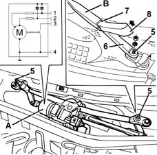
The reservoir, located in the right wheel arch, supplies the windscreen/rearscreen washer system pump with the necessary water/anti-freeze mixture for cleaning the front and rear windscreens, in addition, if the vehicle is equipped with headlamp washers, it also supplies this system.The two-way type pump, thanks to the two pipes connected to it, allows the supply of both groups for jets for the front windscreen and the rearscreen.The capacity of the reservoir guarantees a minimum of 25 washing cycles and can vary from a minimum of 5 litres on versions with headlamp washers to a maximum of 6 litres on versions with headlamp washers.The reservoir is made from plastic and has outside seats for housing the rearscreen and headlamp washer pump (if fitted).
FRONT WINDSCREEN WASH/WIPE
The front windscreen wash/wipe assembly has the task of cleaning and washing the front windscreen.There are two types, according to the trim level of the vehicle, standard or de-luxe, which differ considerably through the availability as optional on the de-luxe version of an electronic device for detecting the presence of drops of water on the windscreen (rain sensor).The windscreen wash/wipe system has impressive innovative features.
- The separation of the control electronics from the motor, unlike previous windscreen wiper systems where the two units were together in a single component.
- The windscreen washer intervention strategy defined by 'smart washing'
- The (optional) presence of a rain sensor
Thanks to the control electronics and according to the position of the right steering column switch unit lever, the system is capable of managing the operation of the direct current type windscreen wiper motor with two windings, i.e. two rotation speeds:
- Low speed: 45 ± 5 rpm
- High speed: 65 ± 7 rpm
Components and operation
The Front Windscreen Washer assembly basically consists of the following components:
- two wiper arms fitted with blades; there are two types of windscreen wiper arms: special arms which rest in a lower position (for EEC areas) and traditional arms which do not rest in a lower position (for SAE areas), the blades for the traditional system have a parallel, synchronous movement;
- a direct current electric motor, which enables the movement of the actual arms, which is fitted with a cam (basically comprising an earthed active switch) which informs the electronic control unit if the actual motor is not working; the motor which has a nominal voltage or 12V can operate at voltages between 9 and 16V/ It has a protective thermal switch and circuits for suppressing electro-magnetic interference at both speeds for long wave, medium wave, short wave and ultra short wave frequencies.
- a two-way electric pump which is controlled by the right lever on the steering column switch unit draws the windscreen washer fluid from the reservoir to supply the jets on the bonnet lid via suitable pipes and the jets on the rearscreen shaft bearing.

Multi-purpose switch or right lever
This includes the front and rear wiper controls.All the commands are activated via the lever or the ring nuts on the actual lever.There is also a button on the end of the lever which controls the trip computer functions.Below is a list of the right lever controls:
The operation is achieved by moving the lever on the steering wheel, there are 5 different positions:
- Pos. 1 = No circuit switched on (STABLE) [REST POSITION];
- Pos. 2 = Antipanic function (UNSTABLE) [ANTI-CLOCKWISE DIRECTION];
- Pos. 3 = Intermittent / Automatic (STABLE) [CLOCKWISE DIRECTION];
- Pos. 4 = 1ST SPEED continuous (STABLE) [CLOCKWISE DIRECTION];
- Pos. 5 = 2ND SPEED continuous (STABLE) [CLOCKWISE DIRECTION];
This control is at the end of the lever and is operated by rotating a special ring nut in a clockwise direction in four stable positions corresponding to:
- BASIC TRIM LEVEL: Pos. 1 - Pos. 4 = Increasing wiping frequency;
- DE-LUXE TRIM LEVEL: Pos. 1 - Pos. 4 = Increasing rain sensor sensitivity;
Electronic module (incorporated in steering column switch unit)
This is the electronic control unit which controls the operation of the electric windscreen and rearscreen wiper motors and the smart washing functions. It is mechanically secured to the CASING to which it is electrically connected by means of special terminals.In particular, it controls the operation of the:
- Windscreen wiper (stroke frequency for all trim levels);
- Rearscreen wiper (stroke frequency and power assistance in reverse gear);
- Windscreen washer function ('smart' washing for all versions);
- Rearscreen washer function ('smart' washing for all versions);
- Rain sensor (management of signal coming from sensor - de-luxe version)
| Mode | Tpause [s] | Strokes per minute |
|---|---|---|
| 1 | 4.7 ± 0.2 | 10 |
| 2 | 2.7 ± 0.1 | 15 |
| 3 | 1.7 ± 0.1 | 20 |
| 4 | 1.1 ± 0.1 | 25 |
| Where Tpause is the interval between the end of one windscreen wiper stroke and the start of the next. |
Windscreen washer function
The activation of the control involves the simultaneous operation of the windscreen wiper in the 1st speed following the 'smart washing' mode, or the activation of the electric pump with a delay of 0.5 secs, between the windscreen wiper strokes to allow the washing first and then the wiping of the wet glass.After wipe functionFollowing the activation of the WINDSCREEN WASHER FUNCTION, an additional windscreen wiper stroke is carried out (in 1st seed) after T = 6 secs to remove any traces of fluid from the actual glass.This function is only activated when the windscreen wiper is not switched on (windscreen wiper control lever in position 1 - no circuit switched on).Automatic operation (with rain sensor fitted)
If the right lever is placed in the intermittent/A1 automatic position, the rain sensor is activated.This adjusts the frequency of the windscreen wiper strokes according to the quantity of water on the windscreen. The frequency can vary continuously from 0 (no stroke - glass dry) up to wiping at continuous speed (heavy rain).The activation of the RAIN SENSOR operates a windscreen wiper stroke as feeback.It is also possible to alter the sensitivity of the RAIN SENSOR through the ring nut A1 at the end of the right lever.If the ignition is switched off leaving the lever in the AUTOMATIC position, the RAIN SENSOR places the windscreen wiper system on STAND-BY. When the ignition is later switched on, no wiping cycle is carried out even if a rain sensor is fitted.To restore the AUTOMATIC operation of the system, carry out any of the following manoeuvres on the steering column switch unit wiper control lever:
- moving the lever from the AUTOMATIC position to any other position and returning it to the AUTOMATIC position;
- altering the sensitivity by turning the RING NUT (increasing or decreasing it).
Recovery function
When the rain sensor is supplied, it provides at least six output impulses in the first 200 ms of operation, as illustrated in the diagram.The absence of these six impulses indicates one of the following situations:
- The incorrect operation of the sensor;
- The disconnection of the signal cable;
- The connection of the signal cable to earth;
- The connection of the signal cable to the supply voltage.

The recovery function makes it possible to identify the presence of one of the malfunctions listed previously (but not which one) as follows:
- with the ignition switched on and each time the user places the lever in the intermittent position, the microcontroller supplies the rain sensor for 200 ms. If the six impulses do not arrive from the rain sensor, the system controlling the wiper functions ignores the subsequent information coming from the sensor and follows the logic described in the 'Windscreen wiper Function'. Once an error situation has been verified, the system continues to operate manually until the key off when the error condition is zeroed.
- During normal operation of the rain sensor: if the signal coming from the sensor remains at the low logic level for longer than 2 seconds, the software module for the sensor notifies the software module for the wiper motor that there is a problem. The windscreen wiper motor control system reacts to this information, operating the windscreen wiper according to the logic described in the 'Windscreen wiper Function'.
Windscreen washer/rearscreen washer electric pump
The electric windscreen washer pump is operated via the right steering column switch unit lever.By moving the right steering column switch unit lever towards the driver (unstable position) the two-way pump is electrically supplied in order to be able to supply the front jets; conversely, pushing the lever towards the dashboard causes the rotation of the pump in the opposite direction and the liquid to come out towards the rearscree| ... DATA ERROR - CROPPED TEXT | Ошибка данных - Текст обрезан ... |
|---|