3026114 - Introduction - ELECTRICAL CIRCUIT FOR INSTRUMENTS/INDICATORS
VE.N.I.C.E PLUS ELECTRICAL AND ELECTRONIC SYSTEM
GENERAL CHARACTERISTICS
In conventional electrical systems, functions are activated with the aid of dedicated point-to-point connections.As the number of eletrical/electronic devices on board new vehicles has increased, the connection are becoming more complex and heavy. One reason for this is the complexity of functions implemented in the many electronic units, which require a continual interchange of data. All this makes it more difficult to install new electrical systems and increases the complexity of fault diagnosis.Many problems have been resolved and new electrical systems have been optimised compared to conventional systems by means of networking. This provides a more effective means of managing communication on board the car and for the transfer of information between subsystems via the serial buses present: single wires, pairs of twisted wires or even optical fibres.VE.N.I.CE (VEHICLE NETWORK INTEGRATION COMPONENT ELECTRONICS) ARCHITECTURE
This is an application of the tried and tested multiplexing or (MUX) system The VE.N.I.CE PLUS system optimises the electrical system because each control unit is located in the centre of the functions it manages. This allows minimisation of the power and signal distribution system through the extensive use of serial communication networks.Power distribution takes place through junction units connected to the control elements (relays, actuators etc.) to ensure the maximum electrical protection and the minimum wiring complexity.The wiring architecture is reduced because each system function requires fewer dedicated cables because the wires (ABS, airbag, sidebag) are built into the front, facia or rear wiring harness. This also makes installation easier.Systems of this type offer innumerable advantates; for example:
- sensors in the various subsystems are made available to the network;
- information may be shared;
- similar sensors can be done away with;
- system flexibilty is increased;
- new functions can be added only by modifying the software (developed during the vehicle life),
- wiring design is simplified and the number of connectors is reduced,
- electronic device operating safety is increased to improve the reliability of information transmited,
- an integrated diagnostic function simplifies service operations on electric/electronic components.

Classic solution
The three control units (electronic nodes) require a number (N) of wires for each input/output in order to perform their function. This has created so much wiring that the system is more complex (design and manufacture), more bulky (weight, bulk and cost) and requires some 40 kg of wiring harnesses amounting to a length of more than 2 km. This requirement is likely to double every 10 years because even now one such vehicle may be equipped with 20 to 40 control units (ECUs).The first step that allowed us to reduce the volume and the complexity of the wiring harnesses was to group several electronic functions in a single unit: fewer control units = fewer wires.Examples of integration
The engine control unit (NCM) manages injection, ignition, pollution system and engine cooling etc.

The integration of electrical/electronic functions in a single electronic unit (ECU) has allowed us to improve:
- power consumption management (lower battery usage);
- functionality of appliances because they are managed by a single control unit;
- fault diagnosis due to control unit self-diagnosis.
Multiplexing solution
Involves exchanging information between different electronic units on a single transmission channel (principle already used for the phone network, radio, TV etc.): 1 BUS (2 wires) for all information
This second stage allows a decisive improvement because:
- Wiring is simplified and reduced
- Number of sensors is reduced (sharing of information)
- Electronic units communicate with one another.
In general, in order to send data via multiplexing, we need to define the following with precision:
- transmission channel (wires, optical fibres, radio waves etc.);
- signal type on the channel (voltage, current, light etc.);
- communication protocol (all the rules that allow management of analogue or digital transmission management, code type, address, transmission order, error recording etc.).
Can (controller area network) network structure
To allow the exchange of information, electrical/electronic systems in VENICE PLUS communicate via two physically separate networks known as low speed B-CAN and high speed C-CAN. Data to be shared between the B-CAN and C-CAN networksare managed by the Body Computer which acts as a system gateway because it is equipped with both interfaces. Via this device, two different network architectures are able to connect and convert certain application protocols into equivalent protocols in the other system.In practice, the body computer transfers information from the B-CAN (low speed) network to the C-CAN (high speed) network through the gateway and viceversa. Transfer may take place in two ways:
- directly: i.e. the entire message is copied to the other network exactly as it is;
- fragmented: i.e. the message received is broken down into its fields (signals) and recomposed as a new message by the other network.
Connection of low speed can (b-can)
In order to transfer information, all the electrical/electronic units are connected to the network via integrated, compatible interfaces in order to receive and transmit data.The B-CAN network (low speed) may feature up to 10 nodes (one per each control unit), all connected via a wire pair (CAN BUS). Maximum BUS length must not exceed 20 m and transmission speed is 50 kbit/sec.| The communciation interfaces built into the electronic units for receiving and transmitting data are known as transceivers. |

Example:
- CAN wire or line (H) interrupted
- CAN wire or line (L) interrupted
- CAN wire or line (H) short-circuited to battery (+)
- CAN wire or line (L) short-circuited to battery (+)
- CAN wire or line (H) short-circuited to earth (-)
- CAN wire or line (L) short-circuited to earth (-)
- CAN wire or line (H) short-circuited to wire or line (L)
High speed can (c-can) connection
For the transfer of information, all electric/electronic units relating to the high speed C-CAN chain are equipped with a compatible interface for data reception and transmission.The C-CAN network (high speed) may serve up to 6 nodes (one for each ECU, all connected via a wire pair (CANBUS). Maximum BUS length must not exceed 10 m. Transmission speed is 500 kbit/sec.One fundamental requirement of C-CAN BUS wires is that they should be in plaited or twisted pairs. By winding two electrical wires into a plait or coil, the degee of immunity to electromagnetic interference of external origin is reduced.On the C-CAN network (high transmission speed), the following electronic units are connected to the Body Computer (NBC):
The network interface cannot communicate at all if once of the following situations arises on the C-CAN network:
- interruption of one of the two lines (H and L)
- short-circuit between the two lines (H and L)
- short-circuit between one line (H) (L) on the battery (+),
- short-circuit of one line (H) (L) to earth (-).
Control units connected to the serial line
The following figure shows the control units connected to serial lines.
VENICE PLUS SYSTEM STRUCTURE
The structure of the VENICE PLUS system is as follows:
Basic diagram of ve.n.i.ce architecture showing main nodes
The following diagram shows the main nodes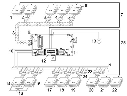
In addition to the two B-CAN and C-CAN networks, the system includes the following serial lines:
- diagnostic k linefor Engine Control Node, Airbag Control Unit, Robotised Gearbox Node,
- W line for immobilizer recovery (Alfa Code), dedicated line between pin 3 NCM and pin 22 NBC
- serial line for Antitheft Siren Control unit/Volumetric Alarm control unit
| the W recovery line allows the release code to be sent to the NCM node when the C-CAN network between the Body Computer (NBC) and the node is working properly |
Eobd connector (electronic on-board diagnostic)
| ... DATA ERROR - CROPPED TEXT | Ошибка данных - Текст обрезан ... |
|---|