3026115 - Introduction - EXTERIOR LIGHTING
LOCATION
OF COMPONENTS ON VEHICLE
The vehicle components and their
location are illustrated below.1 - Right front light cluster
2 - Left front light cluster
3 - Left front direction indicator
4 - Right front direction indicator
5 - Right rear light cluster
6 - Left rear light cluster
7 - Third brake light
8 - No. plate lights
9 - Headlamp alignment control panelCOMPOSITION
The vehicle's exterior lighting system
has been designed with two aims in mind:
- to ensure maximum efficiency in terms of complying with
international regulations which define the illumination specifications
of the various components
- to blend in with the design of the vehicle so that the
various components reflect the image.
In particular, the front light cluster includes
the separate function of the side light, dipped headlamp, main beam
headlamp and fog lights in a single unit.The clear element is made out of one piece
of plastic.TAIL-LIGHT CLUSTER
The vehicle's exterior lighting system
has been designed with two aims in mind:
- Ensuring maximum efficiency in terms of complying with
international regulations which define the illumination specifications
of the various components
- To blend in with vehicle design so that the various
components enhance the image.
- The exterior aesthetic appearance is polychromatic in
line with the vehicle. The functional selection is a light cluster assembled
from a fixed section and a moving section.
The light cluster carries out the following
lighting functions:Signals on fixed section:
- Red incoroporated side light and brake light.
- Orange direction indicator and reflector grouped together.
Signals on moving section:
- 1 red coloured (left) rear fog lamp
- 1 white coloured (right) reversing light
A - Reversing light 12V - 12W (right side only)
B - Direction indicator 12V - 21W
C - Side light 12V - 5W and brake light 12V - 21W (bilux bulb)
D - Connector D
E - Connector E
F - Rear fog lamp 12V - 21W (left side only) right light cluster
CONNECTOR D PIN-OUT
1 - Rear fog lamp
2 - Earth
CONNECTOR E PIN-OUT
1 - Earth
2 - Direction indicator
3 - Brake light
4 - Side lightMoving light cluster lens cover
(F): white (right) reverse or red (left) fog lightFixed light cluster lens cover (B) (C):
two tone orange/redFixed light cluster
This is made from Alfa red coloured
heat resistant ABS. It contains two reflective, parabolic chambers
with brake/side light functions (bilux bulb with two filaments 12V
- 21 - 5W bayonet fitting) and a direction indicator (single filament
bulb 12V - 21W). And a non parabolic chamber for housing the reflector.
It also contains the housing for the sealed, watertight bulb holder;
and the housing for the three fixing studs. The component is fastened
to the side panel.Moving light cluster
It is in Alfa red. It contains
a parabolic reflective chamber for the right reversing light function
(single filament bulb 12V - 21W) and the left rear fog lamp (single
filament bulb 12V - 21W) (reversed for right hand drive versions).
It also contains the housing for the bulb holder. The seal and the
housing for the three studs. The component is fastened to the outside
of the tailgate.FRONT DIRECTION INDICATORS
Below is an illustration of the
front direction indicators.1 - Lit surface smoked lens cover
2 - Bumper grille
3 - Supply terminal
4 - Earth terminal
5 - Casing
6 - Left front direction indicator 12V - 21W
7 - Attachment spring
8 - Screen
9 - O-Ring
10 - Bulb holder
11 - Bulb holder capUse a screwdriver when replacing
the front direction indicator bulb applying leverage at the point
shown by the arrow to extract the complete lens cover outwards.
This operation should be carried out very carefully in order not
to damage the paintwork. Place a cloth between the screwdriver and
the actual bodywork.SIDE DIRECTION INDICATOR
The side direction indicator
is illustrated below.1 - Grey casing
2 - Orange lens cover
3 - Bulb 12V - 5W
4 - Bulb holder
5 - Contact terminal
6 - O-Ring
7 - Prism
8 - Fastening springTo replace the small bulb, push
the lens cover, by hand, in the opposite direction to the direction
of travel of the vehicle in order to compress the fastening spring
(8). Release the front section and extract the unit. Rotate the
bulb holder in an anti-clockwise direction and extract it from the
lens cover.NO. PLATE LIGHT
The no. plate light is illustrated
below.1 - Casing
2 - Lens cover
3 - Spring
4 - Bulb holder casing
5 - Contact
6 - Seal
7 - All glass bulb 12V - 5W
8 - Connector housingThe number plate light function
is achieved by means of two single bulb lights fitted by a metal
spring. Each light has an all glass 12V - 5W bulb which is replaced
by removing the light from the trim and the bulb holder from the
number plate light.The black coloured casing has housings for
fastening to the trim. The polycarbonate lens cover is colourless
and is ultrasonically welded to the actual casing.ADDITIONAL BRAKE LIGHT
The additional brake light function
is achieved through a multi-bulb lamp and light beam coming out
of the rearscreen serigraphy, fitted on the upper part of the tailgate
trim which has a luminous surface.1 - All glass bulb 12V - 2.3 W
2 - Lens cover (red)
3 - Parabola body (black)
4 - Connector
5 - Bulb holder cover (black)
6 - Bulb attachment housing (2-way)The casing is made of black bayblend,
it contains the bulb holder which is in one piece and is fastened
to the actual casing. The internal current carrier tracks are made
from brass with a copper covering and, with the circuit activated,
supply 10 small all glass type 12V - 2.3W bulbs. The light cluster
has two housings for fastening to the tailgate. The red coloured
acrylate lens cover is fitted to the light cluster casing and its
shape and outline give a masked effect with the light off if viewed
from outside the vehicle.The bulbs can be changed, with the light
cluster fitted, through the service cover by opening the tailgate.Fitting brake lights (left/right)
The BRAKE switch has three functional
stages:
- (1a) first condition: with the pedal released the pins
(1 and 3) are closed:
- (2a) second condition: during the travel of the switch
there is an intermediate position in which the pins (1 and 3) and
(2 and 4) are simultaneously closed;
- (3a) third condition: with the pedal depressed the pins
(2 and 4) are closed.
Brake light switch PIN-OUT1 - From fuse F35 dashboard control unit (int. key)
2 - From fuse F37 dashboard control unit (int. key)
3 - From PIN 20 n.c. ABS control unit (NFR)
4 - From PIN 15 dashboard control unit Body Computer - Selespeed
control unit - PIN 69 n.a. - 3rd brake light)Switch: dual contact brake a-
black b- white c-blackNormal brake switch a- black c- whiteClutch switch a- white c- blackBrake lights wiring diagram:A - Braking system control unit (NFR) or ABS
B - Selespeed control unit (NGR)
C - 4-way brake switch with normally closed (n.c.) contacts for
(VDC) function, normally open (n.a.) for brake-ABS-Selespeed function
D - Body computer
E - Right brake light
F - Left brake light
G - 7.5 A fuse F35
H - 10 A fuse F37
I - Supply lines from dashboard control unit
L - 3rd brake lightThe brake lights function is
activated with the ignition key in the ON position (INT) with voltage.Position of switch 1 - 3 normally closed
(n.c.) with pedal releasedPosition of switch 2 - 4 normally open (n.a.)
with pedal releasedWhen the pedal is pressed:
- The voltage signal at PIN 20 of the ABS control unit
(NFR) is removed
- The body computer receives a voltage signal and recognizes
from this that the position of the brake pedal differs from the
rest position (pedal released) and it supplies the brake lights
The body computer (NBC) is capable
of recognizing the following irregularities:
- Open circuit (bulb missing or wiring broken) which can
be diagnosed if there is no command
- Short circuit to earth (bulb short circuited or wiring
short circuited to GND)
- Short circuit to +VB (wiring short circuited to Vbatt)
The continuity of the fuse protecting the
bulbs is also checked.Brake lights position check
The diagram below illustrates
the position of the brake lights.A - Switch
B - Bracket (seen from Y housing detail)
C - Load application point
D - Retaining tooth1 - Press the brake pedal and
fit the brake lights switch (A) on the bracket (B).2 - Position the switch on the bracket rotating
it about 90° in an anti-clockwise direction until you hear the
retaining tooth D click which means it is attached to the fitting
on the bracket B.3 - Release the brake pedal and pull it
backwards with a load applied at point C of 4 +/- 20% daN so that
the brake servo push rod is in the end of travel position (rest
position) and the button is in the correct position in relation
to the switch casing. | this operation must be conducted
carefully because if the switch is not correctly retracted it could
keep the brake pedal in an advanced position with the risk of residual
torque at the wheels which could cause the brakes to lock. |
4 - Move the brake pedal through its full
travel to allow the switch A to bed in.5 - Connect the electrical connection.6 - Check that the brake lights switch is
correctly adjusted in the following conditions: brake lights off
with brake pedal released in rest position and pedal capable of
completing its entire return travel allowed by the brake servo without
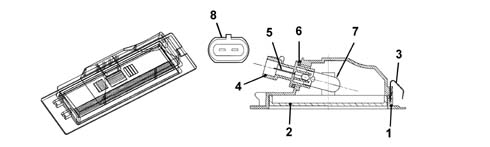
being prevented by the switch.CENTRE SWITCH CONTROL PANEL
The control panel is an electro-mechanical
and electronic unit with LEDs which come on at night and LEDs which
light up the ideograms and controls described below.1 - Tailgate release button
2 - Fog lights control button
3 - Hazard warning lights control button (HAZARD)
4 - Rear fog light control button
5 - Central locking control button
T2 - green LED signalling fog lights on
T3 - red coloured LED with hazard warning lights ideogram (night)
Ideogram with red flashing warning light which is brighter when
the function is switched on
T4 - two tone amber-yellow LED lit up when rear fog lamp is on
T5 - two tone amber-yellow LED lit up when central locking function
is on and red when alarm function is on
T1-T2-T4-T5 - LEDs lighting up ideograms at night with red reduced
brightness
B - centering housings in climate control trimCONNECTOR A PIN-OUT:
- 1 - Positive signal for hazard warning lights LED (flashing)
from (NBC)
- 2 - Earth
- 3 - Negative signal for hazard warning lights control
button from (NBC)
- 4 - INT (ignition key) fuse F49 (dashboard control unit)
for control lights
- 5 - Negative signal from fog lights control button
- 6 - Negative signal from rear fog lamps control button
- 7 - Negative signal from central locking opening/closing
control button
- 8 - N.c.
- 9 - N.c.
- 10 - Negative signal from boot opening control button
- 11 - Positive signal for deterrent LED (alarm on)
- 12 - Negative signal for central locking on LED
- 13 - Positive signal for rear fog lamp warning light
LED
- 14 - Negative signal for fog lights warning light LED
- 15 - N.c.
- 16 - N.c.
- 17 - N.c.
- 18 - N.c.
Switching on direction indicators with warning lights
The direction indicators function
is activated by the following enablements:
- 1- The ignition key in the ON position (INT) with voltage
- 2 - The body computer (NBC) receives commands in the
form of earth signals to turn on the left direction indicator or the
right direction indicator using the steering column switch unit
- 4 - It is always the body computer which manages the
frequency (about 90 cycles +/- 15 per minute) which is sent to all
the bulbs on the branch activated.
- 5 - When the function is activated the left and right
direction indicator warning lights in the instrument panel are lit
up: the instrument panel (NQS) switches on the appropriate warning
lights in harmony with the messages coming from the body computer
(NBC).
Switching on hazard warning lights and warning light
The body computer (NBC) receives
an instruction to activate the hazard warning lights from the unstable
type button in the centre panel. It is an earth signal. The flashing
frequency of the lights; the flashing mode of the warning lights
in the instrument panel (NQS) is identical to the description for
the direction indicators function, but with the difference of all
the direction indicators coming on at the same time.An LED at the back of the control switch
(HAZARD) also comes| ... DATA ERROR - CROPPED TEXT | Ошибка данных - Текст обрезан ... |
|---|