3026024 - 2110B20 manual gearbox (5 speed) with differential - dismantle and rebuild - wash and check parts - replace synchronisers and internal controls if necessary
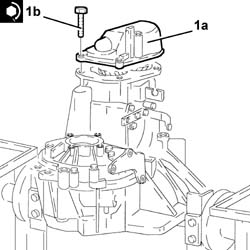
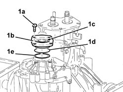
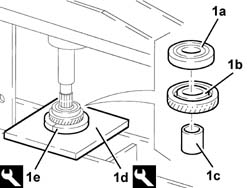
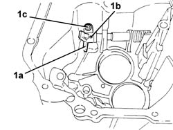
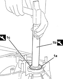
1. Fit the gearbox and differential (1a) on the overhaul stand using the tool (1b).| Two operators are needed for this operation. |
 | Name | Country |
|---|---|---|
| 1b | Mount | 1.820.146.000 |

| Name | Country |
|---|---|---|
| 1b | Flange | 1.820.229.000 |
| Name | Country |
|---|---|---|
| 1c | Counter weight | 1.821.161.000 |
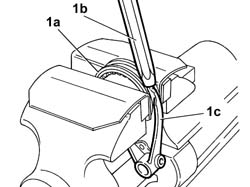
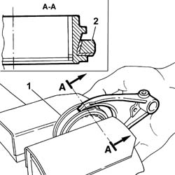
| Replace the retaining clip (1d). |

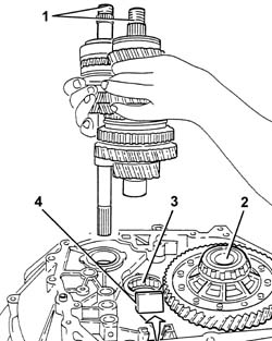
| The simultaneous engagement of two gears will result in the gearbox shafts locking. |
| Take care not to damage the tapered part of the sleeve and the ends of the selector fork with the drift. |


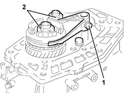
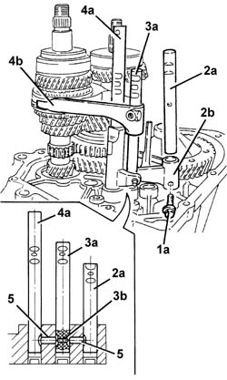
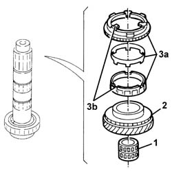
| If the rod offers resistance to being withdrawn, move the other rods (3a) and (4a) to shift the pawls (5) and (3b). |
| Work carefully to avoid the pawl (3b) accidentally falling out. |

| Name | Country |
|---|---|---|
| 1d | Plate | 1.820.047.002 |
| Name | Country |
|---|---|---|
| 1e | Half-rings | 1.870.675.000 |
| Name | Country |
|---|---|---|
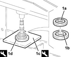
| 1c | Plate | 1.820.047.002 |
| Name | Country |
|---|---|---|
| 1d | Half-rings | 1.870.676.000 |

| When refitting, replace the circplip. |

| Name | Country |
|---|---|---|
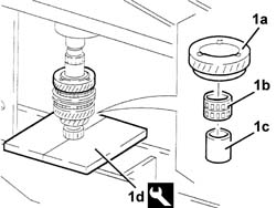
| 1d | Plate | 1.820.047.002 |
| Name | Country |
|---|---|---|
| 1e | Half-rings | 1.870.676.000 |
| The layshaft front bearing inner race should not be refaced; if necessary, replace it together with the layshaft. |

| Name | Country |
|---|---|---|
| 1n | Plate | 1.820.024.000 |
| Name | Country |
|---|---|---|
| 1o | Half-rings | 1.820.017.000 |

| Name | Country |
|---|---|---|
| 1b | Half-plates | 1.820.022.000 |


| Name | Country |
|---|---|---|
| 1d | Half-plates | 1.820.022.000 |
| Name | Country |
|---|---|---|
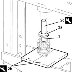
| 2b | Fitting tool | 1.870.659.000 |
| Name | Country |
|---|---|---|
| 2c | Half-plates | 1.820.022.000 |

| Name | Country |
|---|---|---|
| 1b | Fitting tool | 1.870.659.000 |
| Name | Country |
|---|---|---|
| 1c | Half-plates | 1.820.022.000 |

| Name | Country |
|---|---|---|
| 1b | Half-plates | 1.820.022.000 |
| Name | Country |
|---|---|---|
| 1c | Tool for Extracting/Fitting | 1.821.092.000 |

| Name | Country |
|---|---|---|
| 1b | Half-plates | 1.820.022.000 |
| Name | Country |
|---|---|---|
| 1c | Tool for Extracting/Fitting | 1.870.658.000 |

| Name | Country |
|---|---|---|
| 2b | Half-plates | 1.820.022.000 |
| Name | Country |
|---|---|---|
| 2c | Fitting tool | 1.870.659.000 |
| Name | Country |
|---|---|---|
| 1b | Half-plates | 1.820.022.000 |
| Name | Country |
|---|---|---|
| 1c | Fitting tool | 1.870.659.000 |

| Name | Country |
|---|---|---|
| 1b | Grip | 1.821.171.000 |
| Name | Country |
|---|---|---|
| 1c | Fitting tool | 1.821.225.000 |

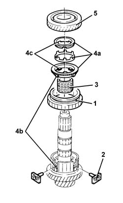
| Make sure that the gear engagement teeth are facing downwards. |
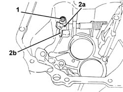
| Position the safety pawl (4c) in the rod before fitting it in the housing. |
 | Fastening | Component | Ø | Value(daNm) |
|---|---|---|---|---|
| 6a | Bolt | 1st - 2nd speed selector fork | M6 | 1.6 ÷ 2.0 |
| Fastening | Component | Ø | Value(daNm) |
|---|---|---|---|---|
| 6b | Bolt | 3rd - 4th speed selector fork | M6 | 1.6 ÷ 2.0 |
| Fastening | Component | Ø | Value(daNm) |
|---|---|---|---|---|
| 7b | Bolt | Reverse selector fork mounting bracket | M6 | 0.9 ÷ 1.1 |

 | Type | Component | Name | Qty. |
|---|---|---|---|---|
| - | Sealant | GEARBOX SEALS/GASKETS | Loctite 573 | - |
| Kepp the gear selector/engagement lever upwards and check that the gear selector engages with the 3rd - 4th speed selector fork. |
| Fastening | Component | Ø | Value(daNm) |
|---|---|---|---|---|
| - | Bolt | GEARBOX GEAR CASING | M8 | 2.3 ÷ 2.8 |
| Fastening | Component | Ø | Value(daNm) |
|---|---|---|---|---|
| - | Bolt | Reverse shaft | M8 | 3.1 ÷ 3.7 |
| To facilitate the fitting of the circlips, place them with their openings at the front. |
| Type | Component | Name | Qty. |
|---|---|---|---|---|
| - | Sealant | GEARBOX SEALS/GASKETS | Loctite 573 | - |
| Fastening | Component | Ø | Value(daNm) |
|---|---|---|---|---|
| - | Bolt | GEARBOX REAR COVER SPACER | M8 | 2.3 ÷ 2.8 |
| When the fitting is complete, check that the sleeve can rotate freely inside the selector fork. |
| Take care to fit the teeth on the seal correctly in the special groove. |
| Fastening | Component | Ø | Value(daNm) |
|---|---|---|---|---|
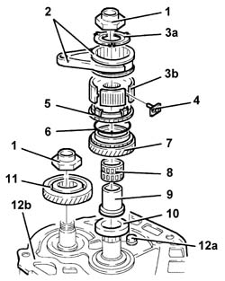
| 11 | Ring nut | GEAR SHAFTS | M20 | 10.6 ÷ 13.0 |
| Fastening | Component | Ø | Value(daNm) |
|---|---|---|---|---|
| 12 | Bolt | 5thª speed selector fork | M6 | 1.6 ÷ 2.0 |

| Type | Component | Name | Qty. |
|---|---|---|---|---|
| - | Sealant | GEARBOX SEALS/GASKETS | Loctite 573 | - |
| Fastening | Component | Ø | Value(daNm) |
|---|---|---|---|---|
| 1b | Bolt | GEARBOX REAR COVER | M8 | 2.3 ÷ 2.8 |