3025236 - 3330D02 brake servo/brake pump assembly - r r
| When removing the battery, make sure also to disconnect the starter motor supply lead, shown in the figure, from the maxi fuse box. |

| Proceed with draining the braking system using the bleed valve on the brake caliper rather than drawing it off from the reservoir using a suitable syringe. |
 | Name | Connector |
|---|---|---|
| 1 | ABS control unit | M50 |


| Take care not to damage the retaining clips. |


 | Fastening | Component | Ø | Value(daNm) |
|---|---|---|---|---|
| 1 | Nut | BRAKE SERVO | M8 | 2.1 ÷ 2.9 |

| Fastening | Component | Ø | Value(daNm) |
|---|---|---|---|---|
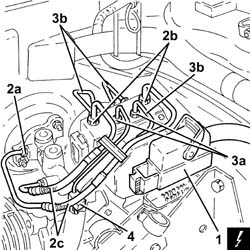
| 1b | Connector | RIGID CENTRE BRAKE PIPES../ | M10/M12 | (A.B.S.) control unit side 1.3 ÷ 1.5 |
| Fastening | Component | Ø | Value(daNm) |
|---|---|---|---|---|
| 2b | Connector | PIPE FROM PUMP TO HYDRAULIC CONTROL UNIT | M12 | (Master cylinder side) 1.3 ÷ 1.5 |
| Fastening | Component | Ø | Value(daNm) |
|---|---|---|---|---|
| 2c | Connector | PIPE FROM PUMP TO HYDRAULIC CONTROL UNIT | M12 | (A.B.S.) control unit side 1.3 ÷ 1.5 |
