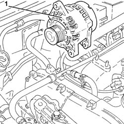
3025525 - 5530A10 alternator - r+r
 | Name | Connector |
|---|---|---|
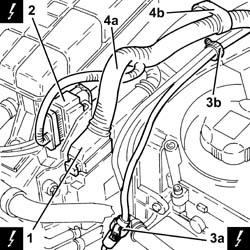
| - | Battery | A1B |
| Name | Connector |
|---|---|---|
| 1 | Engine management ECU | M10B |
| Name | Connector |
|---|---|---|
| 2 | Front / engine coupling | D4 |
| Name | Connector |
|---|---|---|
| 3a | Air conditioning compressor engagement electro-magnet | L20 |
| Name | Connector |
|---|---|---|
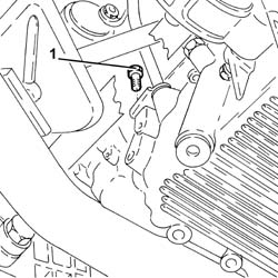
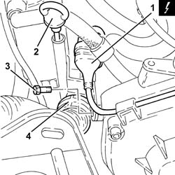
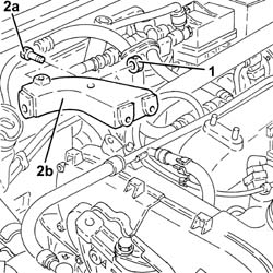
| 1 | Timing sensor. | K47 |
| Name | Connector |
|---|---|---|
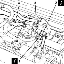
| 1 | Diesel preheating resistor | O20 |
| Name | Connector |
|---|---|---|
| 2 | Fuel temperature sensor | K81 |
| Name | Connector |
|---|---|---|
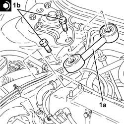
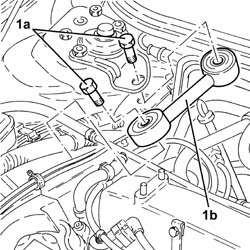
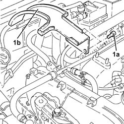
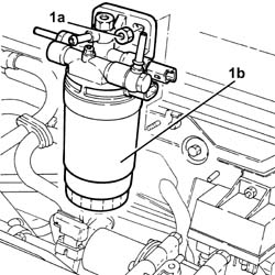
| 1b | Alternator | A10 |
 | Fastening | Component | Ø | Value(daNm) |
|---|---|---|---|---|
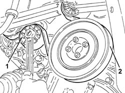
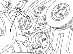
| - | Lower bolt | ALTERNATOR ASSEMBLY | M12 | 6.0 ÷ 7.4 |
| Fastening | Component | Ø | Value(daNm) |
|---|---|---|---|---|
| - | Upper bolt | ALTERNATOR ASSEMBLY | M10 | 4.3 ÷ 5.3 |
| Fastening | Component | Ø | Value(daNm) |
|---|---|---|---|---|
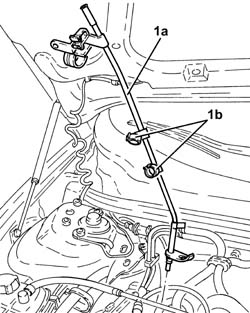
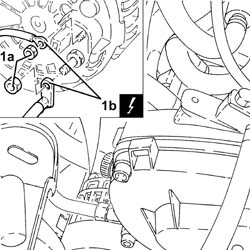
| 1b | Bolt | REACTION ROD | M10 | (Bracket on engine side/bracket on bodyshell) 4.2 ÷ 5.1 |