3363708 - Introduction - GEARBOX
GEARBOXES
The following gearboxes are available for the Stilo
- C514 6 speed for the 1.2 16V version
- C514R 5 speed (R stands for 'reinforced') for the 1.6 16V version
- C510 5 speed for the 1.8 16V version
- C510 5 speed for the 1.9 JTD 80 bhp version
- C530 5 speed with selespeed electrohydraulic unit for the 2.4 20V version
- Getrag 5 speed for the 1.9 JTD 115 bhp version.
Manual gearbox external linkage
The external linkage ensures slick, noiseless manoeuvres.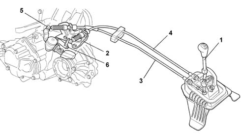
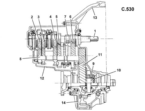
Construction features
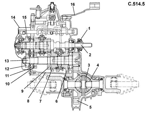
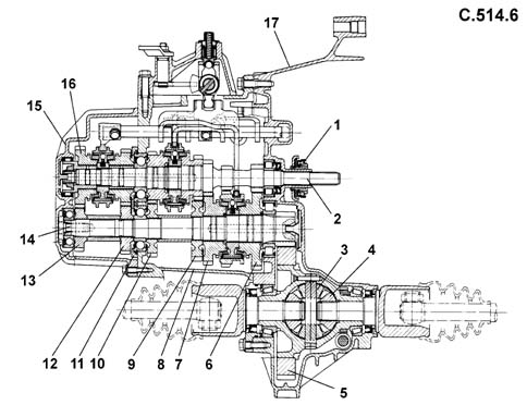
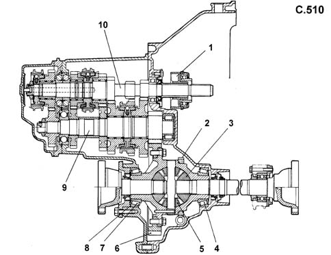
The structure of the gearbox consists of:
- a gearbox casing which contains and supports the main and layshafts, rods and gear selector forks and the gear selector and engagement device.
- a rear cover which contains the 5 speed gears and the rear bearing retaining plate for the main and layshafts (on the C.514.6 gearbox it also contains the 6 speed gears);
- a bell housing which contains the clutch and the thrust bearing.
Main shaft
The main shaft consists of:
- 1st, 2nd speed and Reverse gears fitted directly on the shaft
- 3rd, 4th and 5th speed gears (and 6th for the C514.6 gearbox) fitted on the shaft.
The main shaft is supported:
- by means of two ball bearings for the C510 gearbox
- a front roller bearing and a rear ball bearing are present on the C514 gearbox
- two high-precision taper roller bearings on the C530
Layshaft
The layshaft consists of:
- for the C510 and C514 gearboxes, 1st, 2nd, 3rd, 4th, 5th (and 6th) speed gears fitted on the shaft.
- for the C530 gearbox, 1st and 2nd speed gears fitted on needle bearings with synchronisers, and 3rd, 4th and 5th speed gears fitted to the shaft.
The layshaft is supported on:
- a front foller bearing and a rear ball bearing for the C510 and C514 gearboxes,
- two high-precision taper roller bearings for the C530 gearbox
For all gearboxes, gears are of the following type:
- helical toothed for the forward speeds
- straight toothed for reverse.
Differential
The differential unit is located in the rear of the gearbox casing.On the C510 and C514 gearboxes, this consists of:
- a crown wheel and pinion reduction
- a differential housing constructed in a single piece which includes the differential and planet gears.
On the C530 gearbox this consists of:
- a crown wheel and pinion reduction
- a differential housing made from two half casings which include the planet and satellite gears.
SELESPEED GEARBOX
CONSTRUCTION FEATURES
Gearbox C530
CLUTCH CONTROL
Coaxial hydraulic operation (csc)
The CSC hydraulic system is known as coaxial because it consists of an aluminium actuator cylinder, located in the bellhousing, which is coaxial to the clutch and the main shaft. Thanks to the elimination of external components (selector fork, shaft, release lever) this type of system, which incorporates the hydraulic actuator with the thrust bearing, guarantees improved performance throughout the working life of the vehicle and excellent insulation of the noise and vibrations coming from the power unit.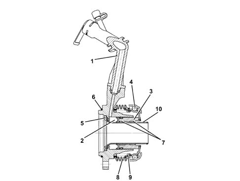
DESCRIPTION OF THE SELESPEED SYSTEM
The following components produce the power-assistance for the clutch and the gearbox control:
- hydraulic supply unit,
- actuator assembly,
- gearbox electronic control unit,
- specific sensors,
- joint sensors.
Hydraulic supply unit
The function of this sub-system is to provide the energy required to move the clutch and gearbox linkage (activated by the driver on a regular version) in a pressure range of between 40 and 60 bar and it consists of:
- hydraulic reservoir (0.5 l)
- electric pump (hydraulic geared pump linked to the commutator type electric motor)
- connecting pipes and connectors.

Actuator assembly
The function of the actuator assembly is to activate the clutch and the internal gearbox controls in order to carry out the gear change stage.The actuator assembly consists of:
- Gear control: this replaces the traditional gear control and allows the operation of the gear linkage in order to implement the gear shift. It includes:
- Valve Assembly: this contains all the proportional solenoid valves and the system hydraulic accumulator.
- CSC: this is the hydraulic actuator that allows the engagement and release of the clutch.
Gearbox electronic control unit
Technologically similar to the engine management control unit, it is located in the passenger compartment.Like all electronic control units it has the task of processing the driver's requests, transforming them into inputs for all the commands needed to satisfy these requests. In order to carry out its tasks the control unit makes use of the information from the High Speed CAN and information from the sensors and potentiometers in specific locations which provide constant information on the operating state.The control unit communicates with the injection control unit through a CAN line and is fitted with a tester line.The following information required for control system operation is taken from the CAN network:
- accelerator pedal position
- engine speed
- vehicle speed
- engine torque.
- brake status (ON/OFF)
SPECIFIC SENSORS:
- Gearbox input shaft speed sensor
- actuator position detection potentiometers
- analogue sensor for detecting hydraulic pressure
JOINT SENSORS:
- engine rpm sensor
- gearbox output speed sensor
- brake pedal switch
- door open switch
Each of the components described above is involved each time there is an input via the following controls:
- UP control on the steering wheel,
- DOWN control on the steering wheel,
- controls on the lever on the tunnel (Joystick)
- AUTO control.
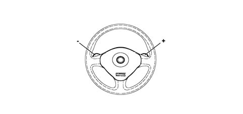
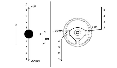
The steering wheel houses 2 control levers:
- UP control on the right side,
- DOWN control on the left side.
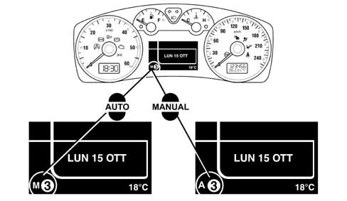
Control panel displays
The control panel displays relate to:
- speed engaged,
- possible auto operation,
- system failure.
COMPOSITION
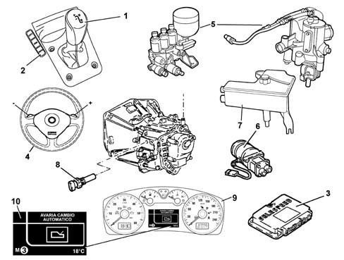
The Selespeed system components are as follows:
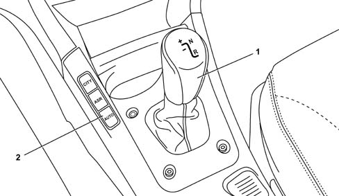
- gear selector lever on the tunnel (1)
- AUTO button (2)
- Selespeed control unit (3)
- gear selector buttons on steering wheel (4)
- solenoid valve unit/actuator assembly (5)
- electric pump (6)
- hydraulic fluid reservoir (7)
- gearbox speed sensor (8)
- gear selection display (9)
- robotized gearbox fault signal (10)
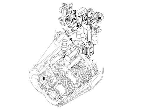
MAIN SYSTEM INTERFACE COMPONENTS
Gear selector lever switch (1)Engine rpm sensor (CAN line from engine management control unit) (2)Vehicle speed (from A.B.S. control unit via CAN line) (3)Gear change buttons (4)Brake pedal switch (5)Oil pressure sensor (6)Driver's door switch (7)AUTO mode button (8)Gearbox input rpm sensor (9)Clutch position sensor (10)Gear selector position sensor (11)Gear engagement position sensor (12)Throttle body integral with D.V.E. (13)Accelerator pedal potentiometer (CAN line from engine management control unit) (14)Proportional pressure solenoid valves (2) (15)On-off solenoid valve (1) (16)Proportional flow solenoid valves (17)Electric pump (18)Buzzer (19)Control panel (20)Diagnostic socket (21)Starter enablement relay (22)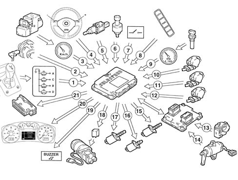
USAGE OF THE SYSTEM
Operations to be carried out for starting/driving vehicle
Stage 1: starting1) Press the brake pedal,2) Start up the vehicle,3) Engage the gear (1st, 2nd or Reverse) for setting off (with the brake pedal pressed), using the lever (when setting off the control on the steering wheel is not received).| With the vehicle stationary and the engine running it is possible to engage 1st gear, 2nd gear or Reverse. The control simply requires an input to engage the gears and then it returns to its central position. |

| The lever control takes priority if simultaneous requests are made using both the steering wheel buttons and the lever. A gear change request is NOT accepted with the car in motion if the request leads to rpm levels that are too high or too low. With the car at a standstill (or virtually still), gear change requests are accepted only if the brake pedal is pressed (applies also to neutral). The steering wheel buttons are disabled when the vehicle speed is below 15 Km/h. |
Horn
A buzzer warns the driver of the following:
- system faults
- improper use (e.g. clutch overheating)
- car safety (e.g. doors open)
Incorrect or inconsistent driver operation
The Selespeed system prevents incorrect driver operation that could cause dangerous situations or be detrimental to the system.The strategies are:
- the lever control takes priority if simultaneous requests are made using both the steering wheel buttons and the lever.
- reverse gear cannot be engaged with the vehicle moving,
- a gear change request is not accepted with the car in motion if the request leads to rpm levels that are too high or too low.
- only 1st gear, 2nd gear and Reverse gear can be engaged with the vehicle stationary and the engine running.
The system has been designed taking into account the possibility that incorrect manoeuvres that could create dangerous situations could be requested allowing:
- the engine can only be started with a gear engaged if the vehicle is stationary, the accelerator pedal released and the brake pedal pressed (the system initially places the gearbox in automatic neutral and then enables the starting of the engine),
- with the car at a standstill (or virtually still), gear change requests are accepted only if the brake pedal is pressed (applies also to neutral). This prevents dangerous situations in case the lever/buttons on the steering wheel are accidentally operated by someone else or even by the driver,
- disabling of the steering wheel buttons at vehicle speeds of less than 15 km/h, thereby preventing possible driver error during parking manoeuvres,
- inhibition of the 'neutral' control above a preset speed, thereby preventing incorrect operation in critical situations, for example, downhill
- AUTO mode cancellation when the driver selects the gear directly using the lever/buttons, the driver's selection takes priority in this situation.
- automatic engagement of neutral and buzzer warning the driver for a limited period in the following cases: insufficient oil pressure for the management of the clutch, engine started and door open (starting with the door open is, however permissible because the driver's action on the brake or the accelerator is detected), engine started with gear engaged and no sign of operation of accelerator or brake for more than 5 secs., gear engaged and accelerator released and brake pedal pressed for at least 30 secs.
- independent gear change if the driver insists outside of the rev range without changing gear.
SYSTEM OPERATION
Turning on the system
This takes place by turning the ignition key. The system informs the driver, through the instrument display, of the gear engaged and, after 1 - 2 secs., the system is capable of accepting new gear changes from the lever only.With the engine switched off
Any gear whatsover can be engaged (including Reverse) and neutral can be engaged; these operations can only be carried out with the brake pedal depressed.Engine start-up
The system only enables the starting enablement relay if the gearbox is in neutral which the system automatically does when the brake pedal is pressed at the time of starting.Vehicle take off / acceleration
Only 1st gear, 2nd gear or Reverse can be engaged for take off after starting. For safety reasons 1st and 2nd gea| ... DATA ERROR - CROPPED TEXT | Ошибка данных - Текст обрезан ... |
|---|