3362746 - 2110A10 MANUAL GEARBOX AND DIFFERENTIAL - R + R
| Description | Connector | |
|---|---|---|
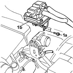
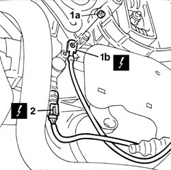
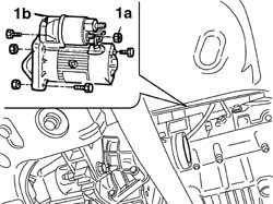
| 1b | Earth on engine | C40 |
| Description | Connector | |
|---|---|---|
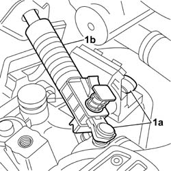
| 2 | Reversing lights switch | I20 |
| Description | Code | |
|---|---|---|
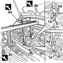
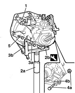
| 2b | Head extractor | 1.847.035.000 |
| Description | Code | |
|---|---|---|
| 2a | Crossmember | 1.870.595.000 |
| Description | Code | |
|---|---|---|
| 2b | Vertical support | 1.870.748.000 |
| Description | Code | |
|---|---|---|
| 2c | Crossmember | 1.860.851.000 |
| Description | Code | |
|---|---|---|
| 2b | Gearbox support | 1.860.873.000 |
| Description | Code | |
|---|---|---|
| - | Gearbox support | 1.860.873.000 |
| Fastening | Component | Ø | Value(daNm) | |
|---|---|---|---|---|
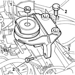
| - | Bolt | MANUAL GEARBOX/DIFFERENTIAL | M12 X 1.25 | (lower gearbox) 5.5 |
| Fastening | Component | Ø | Value(daNm) | |
|---|---|---|---|---|
| - | Nut | MANUAL GEARBOX/DIFFERENTIAL | M10 X 1.25 | (lower gearbox) 4 |
| Description | Code | |
|---|---|---|
| - | Gearbox support | 1.860.873.000 |
| Fastening | Component | Ø | Value(daNm) | |
|---|---|---|---|---|
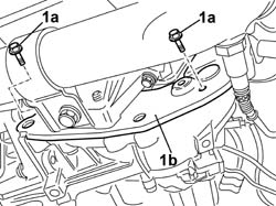
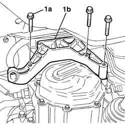
| - | Bolt | MANUAL GEARBOX/DIFFERENTIAL | M10 X 1.25 | (upper gearbox) 8 |
| Fastening | Component | Ø | Value(daNm) | |
|---|---|---|---|---|
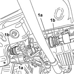
| - | Bolt | GEARBOX SIDE RUBBER MOUNT | M10 | (to the bodyshell vertical wall) 6 |
| Fastening | Component | Ø | Value(daNm) | |
|---|---|---|---|---|
| - | Bolt | GEARBOX SIDE RUBBER MOUNT | M12 X 1.25 | (to the bodyshell horizontal wall) 8.5 |
| Fastening | Component | Ø | Value(daNm) | |
|---|---|---|---|---|
| - | Bolt | POWER UNIT GEAR BOX END RIGID MOUNT | M10 X 1.25 | (gearbox) 3.5 |
| Description | Code | |
|---|---|---|
| - | Crossmember | 1.870.595.000 |
| Description | Code | |
|---|---|---|
| - | Vertical support | 1.870.748.000 |
| Description | Code | |
|---|---|---|
| - | Crossmember | 1.860.851.000 |
| Fastening | Component | Ø | Value(daNm) | |
|---|---|---|---|---|
| - | Bolt | STARTER MOTOR | M8 | (Gearbox) 2.7 |
| Fastening | Component | Ø | Value(daNm) | |
|---|---|---|---|---|
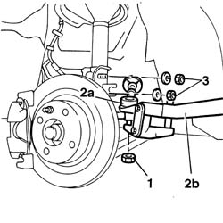
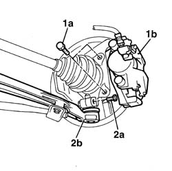
| - | Nut | FRONT LOWER WISHBONE ARTICULATED HEAD | M8 | 3.2 |
| Fastening | Component | Ø | Value(daNm) | |
|---|---|---|---|---|
| - | Bolt | FRONT DISC BRAKE CALIPERS COMPLETE | M10 X 1.25 | 5.7 |
| Fastening | Component | Ø | Value(daNm) | |
|---|---|---|---|---|
| - | Bolt | FRONT HUB STRUT | M10 | 7 |
| Fastening | Component | Ø | Value(daNm) | |
|---|---|---|---|---|
| - | Nut | ADJUSTABLE STEERINGI LINK JOINTS (C-S) | M10 X 1.25 | (to the steering knuckle) 4 |
| Description | Connector | |
|---|---|---|
| - | Reversing lights switch | I20 |
| Description | Connector | |
|---|---|---|
| - | Earth on engine | C40 |
| Fastening | Component | Ø | Value(daNm) | |
|---|---|---|---|---|
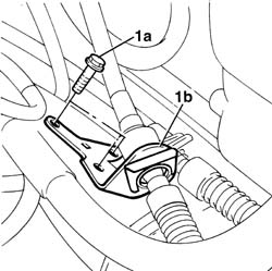
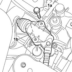
| - | Bolt | CLUTCH CONTROL HYDRAULIC ACTIVATOR | M8 | 1.8 |
| ... DATA ERROR - CROPPED TEXT | Ошибка данных - Текст обрезан ... |
|---|