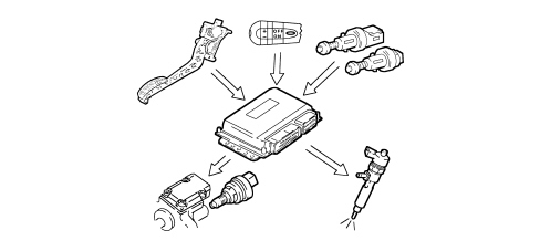
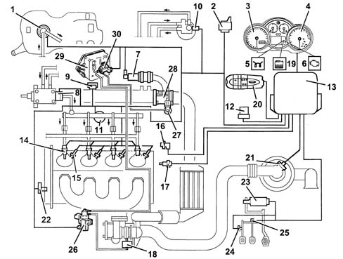
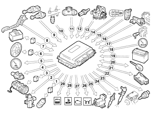
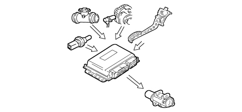
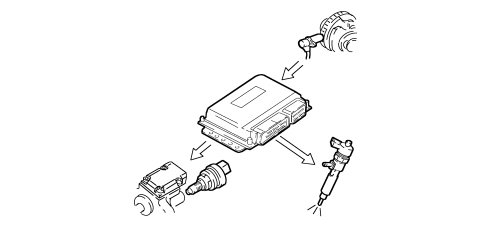
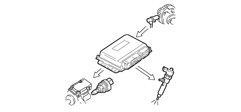
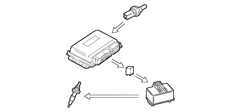
3356182 - INTRODUCTION - DIESEL FUEL INJECTION SYSTEM
SPECIFICATIONS
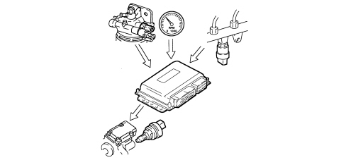
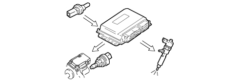
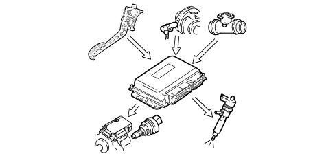
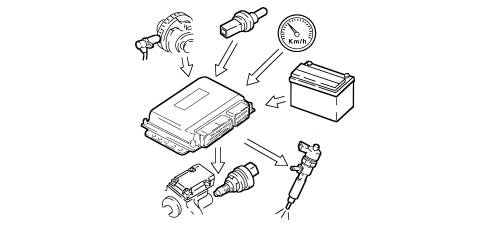
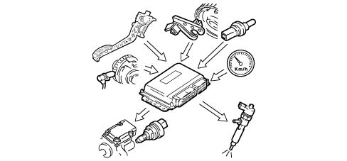
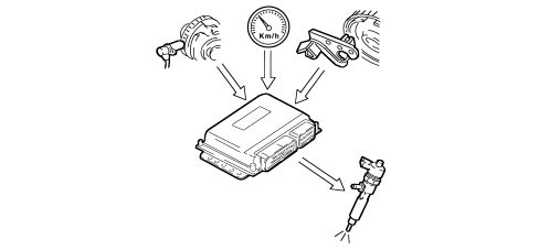
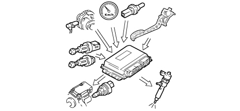
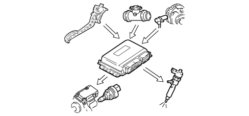
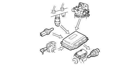
FUNCTION
The EDC-15C7 Common Rail system is a high pressure electronic injection circuit for fast, direct injection diesel engines.Its main features are:
- availability of high injection pressure (up to 1350 bar);
- possibility of modulating pressures between 150 bar up to a maximum service pressure of 1350 bar, regardless of engine speed and load;
- ability to work at high engine rpm (up to 6000 rpm);
- injection control precision (injection advance and duration);
- reduction in fuel consumption;
- reduction in emissions.
Main system functions are essentially as follows:
- fuel temperature control;
- engine coolant temperature control;
- control of amount of fuel injected;
- idle speed check;
- fuel cut-off during over-run;
- cylinder balance check when idling;
- control of anti-judder function;
- exhaust fumes control during acceleration;
- exhaust gas recirculation control (E.G.R.);
- maximum torque limit control;
- maximum speed limit control;
- control of glow plugs;
- control of climate control system activation (where fitted);
- auxiliary fuel pump check;
- cylinder position check;
- main and pilot injection advance check;
- injection pressure closed cycle check;
- electrical balance check;
- supercharging pressure control;
- self-diagnosis;
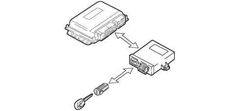
- connection with FIAT CODE control unit (Immobilizer).
OPERATION
Operating strategies
Introduction
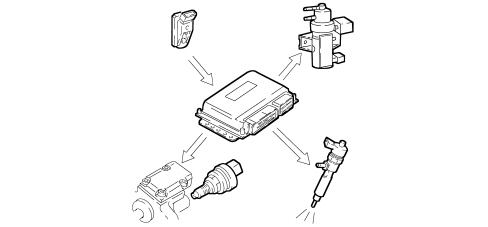
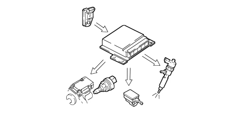
The Common Rail system makes it possible to carry out a pre-injection (pilot injection) before T.D.C. with the advantage of reducing the consequences of the pressure in the combustion chamber and reducing the combustion noise typical of direct injection engines.The control unit controls the quantity of fuel injected, regulating the line pressure and injection times.The control unit processes the following information to control the quantity of fuel to inject:
- engine rpm;
- coolant temperature;
- supercharging pressure;
- air temperature;
- intake air quantity;
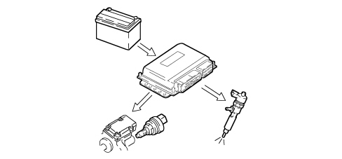
- battery voltage;
- diesel pressure;
- accelerator pedal position.
SIGNALLING OF FAULTS DURING STARTING:
- warning light on for 4 seconds indicates test stage;
- warning light off after 4 seconds indicates no fault with components that can alter values set out by pollution control regulations;
- warning light on after 4 seconds indicates fault.
SIGNALLING OF FAULTS DURING OPERATION:
- warning light on indicates fault;
- warning light off after 4 seconds indicates no fault with components that can alter values set out by pollution control regulations.
When the engine coolant temperature is above 105°C, the control unit:
- reduces injected fuel quantity (reduces engine power);
- controls the cooling fans;
- switches on the coolant temperature warning light.
On the basis of the signals coming from the sensors and the values stored, the control unit:
- controls the pressure regulator;
- alters the "pilot" injection time up to 3000 rpm;
- alters the "main" injection time.
The control unit processes the signals coming from the various sensors and regulates the quantity of fuel injected:
- controls the pressure regulator;
- alters the injector injection times.
During the accelerator pedal release stage, the control unit implements the following logics:
- cuts off the supply to the injectors;
- partly reactivates the supply to the injectors before the idle speed is reached;
- controls the fuel pressure regulator.
According to the signals received from the sensors, the control unit controls the idle speed torque:
- alters the quantity of fuel injected by the individual injectors (injection time).
The control unit processes the signals received by the various sensors and corrects the quantity of fuel to inject in order to improve driveability reducing shuddering whilst driving by means of:
- the pressure regulator;
- the injector opening time.
In order to restrict the fumes during fast transitions, on the basis of the signals received from the flow meter and the engine speed the control unit limits the amount of fuel to be injected by means of:
- the pressure regulator
- the injection time.
In accordance with EURO 3 pollution control legislation, on the basis of the engine load and the signal from the accelerator pedal potentiometer, the control unit limits the quantity of intake air, implementing the partial intake of exhaust gases, through:
- the adjustment of the opening of the E.G.R. valve
According to the rpm level, the control unit calculates the following in pre-defined maps:
- the torque limit;
- the permitted fumes (limit).
It compares this minimum values and corrects them with other parameters:
- coolant temperature;
- engine rpm;
- vehicle speed,
Depending on the rpm, the control unit implements two operating strategies:
- at 5000 rpm it cuts off the fuel reducing the line pressure;
- beyond 5400 rpm it deactivates the auxiliary pump and the injectors.
The injection unit, during the following stages:
- starting;
- post-starting
- applies a timer to the glow plug preheating control unit based on engine temperature.
The control unit operates the air conditioning compressor:
- switching it on/off when the switch is pressed;
- switching it off momentarily (about 6 secs) in the case of strong acceleration or a request for maximum power.
Irrespective of the rpm, the control unit:
- supplies the auxiliary fuel pump with the ignition ON;
- cuts off the auxiliary pump supply if the engine is not started within a few seconds.
According to the battery voltage, the control unit alters the idle speed:
- increases the injector injection times;
- modulates the line pressure.
The control unit processes the signal from the supercharging pressure, at the various engine operating speeds and determines the quantity of fuel to inject:
- controls the pressure regulator;
- alters the injection time;
- regulates the turbine geometry to ensure optimum performance in all operating conditions.
The control unit processes the signal from the supercharging pressure, at the various engine operating speeds and determines the quantity of fuel to inject:
- controls the pressure regulator
- alters the injection time
- controls the supercharging solenoid valve (waste-gate).
Depending on the temperature of the coolant and the pressure of the refrigerant fluid in the air conditioning system, the control unit controls:
- fan activation at first or second speeds.
The cruise control is temporarily disabled:
- by operating the brake,
- by operating the clutch;
- the recall button returns to the stored speed.