3363853 - Introduction - PANELS AND FRAME
SPECIFICATIONS
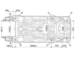
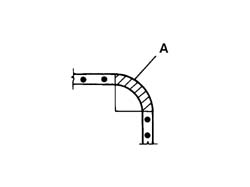
The following figure shows the
underbody dimension specificationsThe comparative dimensions, expressed in
millimetres, may vary slightly in relation to those stated, and
the mechanic will be able to determine by experience whether this
is due to the impact or to manufacturing tolerances.
A. Engine suspension
B. Front suspension
C. Rear suspension
D. Main body reference
SPECIFCATIONS
REPAIRING THE VEHICLE
General safety warnings
The activities connected with
repairing the bodywork involve the use of equipment and tools in
addition to the handling of chemical products and substances for
which the supplier's instructions must be followed.It is therefore necessary to pay
special attention to:
- The correct use of materials, instruments and equipment:
before carrying out any sort of operation, read the instruction
manuals carefully and follow the accident prevention and safety
instructions with great care.
- The workplaces for carrying out operations, which should
have appropriate ventilation systems which satisfy the legal requirements
concerning air exchange, the filtration of harmful substances (solvents)
and the reduction of dust levels.
- The handling of dangerous substances which should be
carried out in accordance with the supplier's instructions and recommendations.
The collection and disposal of refuse which
should be carried out in accordance with the laws in force.When working with and handling harmful and
dangerous substances, the appropriate safety equipment should be employed
(clothing, masks, gloves, goggles, etc.).Vehicle repair operating cycles
The vehicle repair operating cycles
usually consist of the following stages:
- checking the vehicle measurements;
- cutting/removing damaged elements and preparing the
bodyshell for welding;
- welding replacement elements;
- preparing for painting;
- painting;
- renewing the anti-corrosion treatments;
- sound insulation, sealants.
Checking and restoring the vehicle measurements
This is the first stage in the
repair process in which the distortion suffered by the bodyshell
is measured and evaluated and the components involved are identified.During this stage the first actual repair
operation is carried out: pulling the bodyshell to restore the measurements before
cutting and removing the damaged elements.Pulling the bodyshell
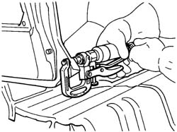
Pulling the bodyshell, to restore
the measurements, is carried out on straightening benchs where it
is possible to secure the bodyshell using vices and attachments
which should be fixed according to specific methods for each vehicle,
with instructions provided by each supplier.Jigs are used to check the measurements
of the bodyshell. They are positioned at specified points, and are
used to check the measurements indicated by the jig manufacturer for
each model, or alternatively the vehicle's own measurements given
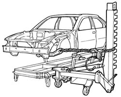
in the section 'Descriptions and Operation'.Example of a possible straightening bench
configuration.General repair instructions
. | Before carrying out any sort of
operation on the vehicle, disconnect the battery terminals. |
For safety reasons and for a better
quality repair, IT IS PROHIBITED TO:
- replace structural parts of the bodyshell without using a
repair bench. The use of the bench makes it possible to guarantee
the restructuring of the vehicle with the original manufacturing
measurements, ensuring the correct position of the forecarriage
and back-carriage elements.
- heat the structural parts of the bodyshell to straighten them.
- cut and weld, edge to edge, any bodywork element and
reinforcement on the same line.
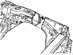
Remove the damaged elements, cutting them
on the joins, following the cutting lines given in the Service Manual. Carried
out correctly, the operation involves wasting a few centimetres
between the two cutting lines in order to improve the distribution
of the fusible points created by the welding.The diagram below illustrates a possible
implementation.. | The removal of the damaged elements
is the repair operation during which the potentially most dangerous
equipment is used. Before carrying out any operation, read the safety
instructions in the manual very carefully and follow the warnings
from the manufacturer of the equipment in conjunction with the safety
and accident prevention recommendations. |
The use of the following is required
for the removal of damaged body panels:
- hack-sawing machines;
- circular saws;
- power chisels (only in case of need);
- plasma-arc cutting systems;
- electric drills;
- milling machines;
- grinding machines;
- dolly blocks and hammers;
- disc grinding wheels;
- air purifiers / extractor systems.
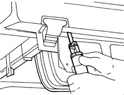
Hack-sawing machine
This type of saw makes it possible
to carry out fast and precise cutting, with the possibility of regulating
the speed of the blade to suit different situations.Example of the use of a hack-sawing machineOscillating circular saw
An oscillating saw is used in
cases where high cutting precision is required; for example, when
you need to replace the sheet metal of a box section that is laid
over a panel which must not be damaged. By adjusting the speed and the
number of oscillations it is possible to achieve the precision required
according to the conditions of use. The high level of safety of
this instrument makes it advisable to use it as an alternative to
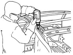
other types of saws.Example of an oscillating circular sawPower chisel
A pneumatic chisel is used to remove
parts of body panels; it is advisable to use it:
- when it is not possible to use a power saw, milling machine
or drill; for example, when a panel that must not be damaged lies
behind the panel that requires cutting;
- when it is possible to directly separate the welded panels,
inserting the power chisel between the two panels along the join
edge in order not to leave edges which need removing later on.
The different attachments increase its versatility.Example of the use of a power chiselPlasma-arc cutting system
This cutting system, achieved
through the combined effect of an electric arc and gas or a mixture
of gases, is used whenever it is necessary to cut rather large panels. Depending
on the thickness of the panel and the depth of the cut, adjust the
current and the gas flow following the instructions in the Manufacturer's
booklet. | The use of a plasma-arc cutting
system requires the use of an extractor system to get rid of the fumes
and harmful gases. |
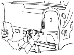
Electric drill
An electric drill is normally
used in cases where a milling machine cannot be used; the correct
use of the drill to remove spot welds if several panels are superimposed
is illustrated in the diagrams below. The attachment to be used
in these operations is identical to the one fitted on the milling
machine. The spot weld should be marked using a drift, in order
to provide a support point for the centring bit, this prevents the
drill moving away from the spot and damaging the surrounding area;
force should be exerted on the cutter until the depth reached is
slightly greater than the thickness of the panel which should be
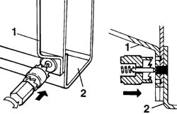
removed (see diagram below).Example of the use of an electric drillExample of the correct usage
of a milling cutter
1. Panel to be removed.
2. Box section panel preventing the use of a milling cutter.
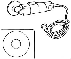
Milling cutter
A milling cutter for removing
weld spots should be used after cutting the panel to be replaced
in order to allow the removal of the panel offcuts remaining on
the edges of the bodyshell.The milling cutter acts on the panel which
constitutes the offcut, cutting it as far as the panel underneath
and thereby isolating the spot weld.After the reduction of all the spot welds.
the offcut is removed using pliers.To facilitate the operation, use a cutting
speed of around 1000 rpm.Adjust the depth of the cutting using the
special screw.Example of the use of a milling cutter. | Do not drill matching components.
If holes are made by mistake, close them by (MIG) welding. The presence
of holes reduces the strength of the component involved and can
also give rise to the penetration of water and corrosive agents. |
Dolly blocks and levers
These instruments are used when
panels need to be straightened by beating, in order to have a counter-action point
to support the panel. Dolly blocks are designed so that they adjust
to the different panel conformations and, when the working area
permits, they can replace a hammer.Levers are used in the same way as dolly
blocks, however they are designed so that they can be introduced
through restricted openings and spaces to get to areas which are difficult
to reach.Dolly blocks and levers are also used to
eliminate distortions from the edges of panels which are not removed thereby
allowing correct matching with the replaced panels, avoiding weakening
the structure.Welding replacement elements
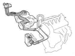
If welding operations or work
which could produce flames near the fuel system components illustrated
in the diagram or other flammable parts of the vehicle need to be
carried out, the parts involved must be removed from the vehicle and
the free pipe connections sealed if the connectors are removed.
Disconnect the electronic control units (I.E., ABS, Air Bag, Air
conditioning, Alarm, etc.) which could be damaged during the work.Parts of the fuel systemWelding bodywork elements should
be carried out, according to requirements, using different methods:
- Spot welding;
- Seam (MIG) welding;
- Brazing.
Equipment
The following equipment is used for
these operations:
- welding guns;
- seam (MIG) welders;
- oxyacetylene torches (brazing).
Introduction to electrical spot welding
In electrical spot welding the
heat needed to melt the metal is supplied by the resistance to the
current flow provided by the actual metal.Spot welding is carried out to panels where
the join edges overlap and the panel metal melts; no metal filler
is therefore needed for this type of welding. In areas where three or
more panels overlap, spot welding should be repeated for a second
time.The type of join produced is not continuous;
to create a join with good mechanical strength the spot welds must
be correctly spaced following precise instructions (see tables below).Spot welding
In the case of spot welding, check::
- that the arms are correctly aligned;
- that the diameter of the edges of the electrodes is
correct;
- the planarity and that the weld edges are correctly matched;
- that the welding sequence is correct.
| Before welding, apply electro-weldable
galvanizing protection to the edges of the join to protect the box
sections from corrosion. |
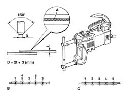
Spot welder, geometric characteristics of
the electrode according to the thickness of the panel and the welding sequence.
A. Electro-weldable galvanizing protective
B. Correct welding sequence
C. Incorrect welding sequence
D. Electrode dimensions
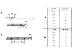
Table of reference values for
carrying out spot welds.
A. Table for determining the distance of the spot welds from
the edges of the panels according to their thickness.
B. Table of reference values for the correct spacing of the spot
welds according to the thickness of the panel.
Do not weld on angular shaped
surfaces. Welding on this type of surface would create a concentration
of tension which would result in breakage.Example of correct spot welding at corners.
A. Area where welding should not be carried out.
Seam (mig) welding
MIG welding should be used for parts
where spot welding cannot be used. When carrying out seam (MIG)
welding, check:
- the speed
- that the seam weld beads have been correctly made (alternating
weld sections)
In this welding system (automatic advance
seam) a protective inert gas atmosphere is used (hence the name
M.I.G. which stands for Met| ... DATA ERROR - CROPPED TEXT | Ошибка данных - Текст обрезан ... |
|---|