3360157 - 5505A multi-function components
BODY COMPUTER NODE E04 (NBC)
SPECIFICATIONS
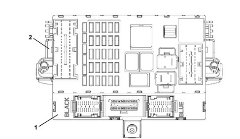
The BODY COMPUTER NODE manages some of the vehicle's electrical system functions.The NBC is housed under the dashboard near the steering column, in a central position in relation to the functions that it manages.The Body Computer Node (NBC) together with the Dashboard Control Unit (CPL) form the DASHBOARD NODE (NPL) where the former (NBC) constitutes the electronic section and the latter (CPL) the electro-mechanical section.The fuses and relays are fitted on the CPL, whilst the NBC houses the EOBD fixed connector used for the fault diagnosis via the K lines of the NCM, NFR, NCR and CAB.This is connector is also prepared for the dialogue with the B - CAN and C - CAN networks which can be used for both fault diagnosis and for possible on line programming.BODY COMPUTER NODE GENERAL FUNCTIONS
The NBC peforms the following functions:
- It receives and sends information on the B - CAN network (e.g.: fault diagnosis, warning lights, commands, data)
- It receives and sends information on the C - CAN network
- It interconnects with the dashboard, front and rear wiring
- It allows an interface for the fault diagnosis (EOBD)
- It connects to the CPL to take power supplies / signals and operate relays.
We find the following functions:
- management of the centre front courtesy light (20W) with timed switching off and dimming
- management of the two spot lights (10W) with timed switching off and dimming
- management of on/off exits at relay: headlamp washer pump, main beam headlamps, fog lights, dipped headlamps, services, heated rear windscreen
- on/off management of relay during right/left direction indicators or hazard warning lights for acoustic feedback
- management of on/off exits directly at loads and diagnostic function: front side lights (left and right), rear side lights (left and right), front direction indicators (left and right), rear direction indicators (left and right), side direction indicators (left and right), no. plate lights (left and right), brake lights (left and right), rear fog lamps (left and right);
- management of on/off exits directly at loads: heated rear windscreen LED, hazard warning lights LED, management of the sun roof;
- repetition of the vehicle speed signal
- management of the ideogram light (15W) driver
- management of the SBMT (35W) driver
- management of the recovery serial line to the engine management control unit (immobilizer)
- management of the serial line to the volumetric sensors, siren, anti-tilt, rain sensor, dusk sensor, steering column switch unit, tyre pressure control unit.
- master for the entire system: management of the IFRs at the slave nodes under direct jurisdiction and monitoring of the IFRs by the other master nodes, monitoring and management of protocol errors, timer control;
- fault diagnosis of the entire system: collection of diagnostic information, management of the fault diagnosis using the Fiat Lancia Tester
- anti-theft: management of the remote control receiver (RF) (excluding NBC192-FULL version), connection with volumetric sensors, the siren and the anti-tilt
- immobilizer: management of the key code with possible engine immobilizing
- acquisition of on/off signals: dipped headlamp operation, main beam headlamp operation, boot lock opening control, boot locking function, handbrake control, hazard warning lights control, left and right rear fog lamps control, fog lights relay feed, left direction indicators control, right direction indicators control, parking lights control, side lights control, city control, steering column switch unit auto control, headlamp washer control, FIS control, boot button, bonnet button, front brake pad wear (left and right), brake fluid level, reverse gear engaged;
- acquisition of analogue signals: fuel level, alternator voltage (D+), battery voltage, brake lights fuse status recognition, centre courtesy light control, left and right spot lights control, brake lights control
- acquisition of vehicle speed signal
- acquisition of lock sensors from door.
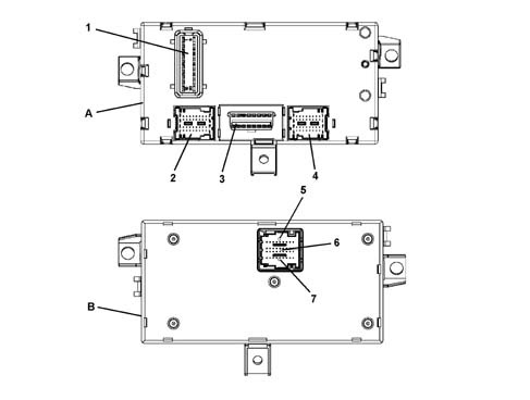
BODY COMPUTER NODE NBC PIN OUT
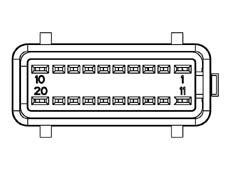
M01F connector (20 way)| Conn. | Pin | Function |
|---|---|---|
| M01F | 1 | +30 from F-38 for boot release geared motor |
| M01F | 2 | Button on brake pedal status input |
| M01F | 3 | Button for switching on reversing lights status input (connection with M01A 1) |
| M01F | 4 | Not available |
| M01F | 5 | Low speed CAN line (connection with M01G 6, M01D 6, M01A 27, M01C 24) |
| M01F | 6 | Heated rear windscreen relay control output |
| M01F | 7 | Low speed CAN line (connection with M01G 14, M01D 5, M01A 26, M01C 25) |
| M01F | 8 | Dipped headlamp relay control output |
| M01F | 9 | Track from fuse F51 and ignition lock position status input (connection with M01F 15) |
| M01F | 10 | Preparation for boot lock |
| M01F | 11. | Boot release geared motor control |
| M01F | 12. | Lock position input on parking condition |
| M01F | 13 | INT from F-37 for NQS, CPS, CPD and brake lights fuse status input (connection with M01B 31, M01A 10) |
| M01F | 14 | Additional service relay control output |
| M01F | 15 | Track from fuse F51 and ignition lock position status input (connection with M01F 9) |
| M01F | 16 | Not available |
| M01F | 17 | Track towards CPL wiring (+12V) for front, rear courtesy light, NCL siren, CAV, diagnostic socket (connection with M01A 11, M01A 34, M01C 26, M01G 16, M01E 27, M01E 39) |
| M01F | 18 | Power supply for body |
| M01F | 19 | Dedicated power supply for direction indicators and hazard warning lights (connection with M01D 3) |
| M01F | 20 | Dedicated earth for release geared motor (preparation) |
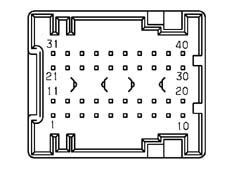
| Conn. | Pin | Function |
|---|---|---|
| M01E | 1 | Driver's door open status input for NCR (connection with M01E 8) |
| M01E | 2 | Not available |
| M01E | 3 | Right rear direction indicator control output (21W) |
| M01E | 4 | Fuel level input |
| M01E | 5 | Left rear side light control output (5W) |
| M01E | 6 | Right rear side light control output (5W) |
| M01E | 7 | A-bus serial line for anti-theft (connection with M01A 25) |
| M01E | 8 | Input signal from normally open switch signalling driver's front door open (connection with M01E 1) |
| M01E | 9 | Left no. plate light control output |
| M01E | 10 | Sun roof control unit output |
| M01E | 11. | Not available |
| M01E | 12 | Left rear direction indicator control output (21W) |
| M01E | 13 | Not available |
| M01E | 14 | Hanbrake lever button status input |
| M01E | 15 | Fuel level input |
| M01E | 16 | Left rear door open status input |
| M01E | 17 | F.I.S. signal input |
| M01E | 18 | Serial line for CPP (connection with M01G 13) |
| M01E | 19 | Signal coming from city button in dashboard |
| M01E | 20 | Right rear fog lamp control output |
| M01E | 21 | Centre courtesy light control output |
| M01E | 22 | Right brake light control output |
| M01E | 23 | Interior lights control output (luggage compartment) (connection with M01E 33, M01C 15, M01C 16) |
| M01E | 24 | Signal from boot lock catch (locking enablement) |
| M01E | 25 | Input signal from normally open switch signalling front passenger door open (connection with M01E 11) |
| M01E | 26 | Input signal from normally open switch signalling right rear door open |
| M01E | 27 | Track towards CPL wiring (+12V) from F39 for front/rear courtesy light (connection with M01F 17) |
| M01E | 28 | Analogue input for switching on left/right spot light and excluding front/rear courtesy light in centre courtesy light |
| M01E | 29 | Not available |
| M01E | 30 | Left spot light control in centre front courtesy light |
| M01E | 31 | Left rear fog lamp control output |
| M01E | 32 | Left brake light control output |
| M01E | 33 | Passenger compartment interior lights control output (left and right) (connection with M01E 23, M01C 15. M01C 16) |
| M01E | 34 | Signal from boot lock catch (release enablement) |
| M01E | 35 | Signal from opening switch on boot handle |
| M01E | 36 | Signal from normally open switch signalling boot open |
| M01E | 37 | Right spot light in centre front courtesy light control output |
| M01E | 38 | Right no. plate light control output |
| M01E | 39 | Track towards CPL wiring (+12V) for CAV (connection with M01F 17) |
| M01E | 40 | Internal serigraphy lighting control output (connection with M01C 18) |
| Conn. | Pin | Function |
|---|---|---|
| M01G | 1 | Serial line for NFR (connection with M01A 16) |
| M01G | 2 | Not available |
| M01G | 3 | Serial line for Air Bag CAB (connection with M01C 12) |
| M01G | 4 | Power earth (connection with M01D 9) |
| M01G | 5 |
| ... DATA ERROR - CROPPED TEXT | Ошибка данных - Текст обрезан ... |
|---|