3363710 - Introduction - STEERING
ELECTRIC STEERING
SPECIFICATIONS:
The Stilo is equipped with electric power assisted steering.This system has the task of producing a force which, applied to the force applied to the steering wheel by the driver, reduces the physical effort required for manoeuvring.The system comprises a steering box with a conventional rack, an electric motor with the rack fitted to the steering column, a so-called 'force' sensor (it senses the force applied to the steering wheel), a button (with City or Normal positions) and a control unit which manages the operation.The assistance together with that of the driver's, depends on the following parameters:
- force applied by the driver
- vehicle speed
- steering angular position
- steering angular speed
- level of assistance (City or Normal)
In all operating conditions the system:
- keeps the effort required for steering below a certain level and dependent on the level of assistance selected (City - Normal)
- ensures the correct return to the centre of the steering wheel during realignment
- ensures the damping of steering wheel vibrations during return to the centre
Electric power assisted steering offers the following advantages compared with hydraulic power assisted steering:
- the system has a smaller number of components and is therefore lighter and less complex
- it takes less time to install and is simpler to service
- the electric power assisted steering system only absorbs power when power assisted steering is required, improving the performance of the vehicle and reducing consumption and emissions
- greater driving comfort resulting from less operating noise
- a reduction in pollution because electrical energy is used
- a variation in the power assistance according to the vehicle speed
- power assistance which can be selected according to the customer's requirements (City/Normal)
Basic strategies
According to the driver's requirements and the speed of the vehicle, the control unit operates the electric servomotor which assists the rotation of the steering column.The motor applies a force to the steering column, by means of a worm screw mechanism, decreasing the effort required from the driver when steering.Power assistance which varies according to the speed of the vehicle
As the speed of the vehicle increases, the driver proportionally increases the force applied to the steering wheel; as the speed of the vehicle increases, the resistance at the wheels decreases.As a result, the control unit, using the speedometer signal, implements a reduction in pressure.Active return
The return stage refers to the realignment function normally produced by the geometry of the front section of the vehicle when the steering is released after a steering manoeuvre.This function is designed to make this realignment faster, causing the servo motor to intervene and assist the normal geometry effect.The correction of the return varies according to the speed of the vehicle:
- it is maximum at low speds,
- it is minimum at high speeds
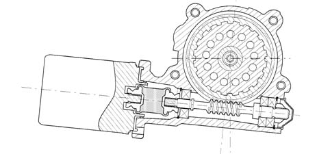
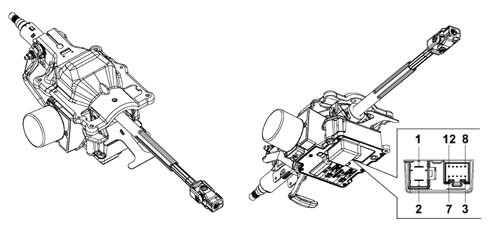
Geared motor
The geared motor unit consists of an aluminium casting fastened to the vehicle chassis.The geared motor gear, coaxial and joined to the steering column, is made of steel, whilst the outer ring gear is made from pressed plastic.The metal part of the gear is fitted on the output shaft, which transmits the steering forces (in other words the torques from the servomotor and the driver).The input and output shafts are connected to one another by a 'calibrated torsion beam'.Where there is resistance at the wheels, the input shaft weakens (NOT irreversibly) the torsion bar, therefore the input shaft and the output shaft are offset at an angle proportional to the force applied to the steering wheel.A torque sensor, fitted inside the geared motor, detects the change in angle, between the input shaft and the output shaft and supplies an electrical signal to the control unit proportional to the shift.The geared motor unit casing also has the task of retaining the outer part of the 'torque and position sensor'.Lastly, the input shaft support cover, where the steering wheel is fitted, is secured to the casing and it houses both the ignition switch and the steering column switch unit.Electric steering pin out
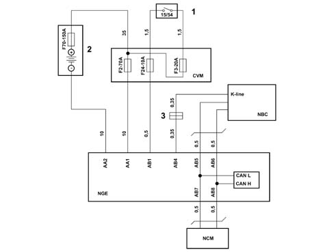
The control unit has two connections:
- one two-way supply,
- one 10-way for connection to the CAN.
| Pin | Function |
|---|---|
| 1 | Battery power supply (+) |
| 2 | Battery return (-) |
| 3 | Key on signal |
| 4 | City signal |
| 5 | N.C. |
| 6 | Line K (diagnostic) |
| 7 | CAN bus |
| 8 | CAN bus |
| 9 | CAN bus |
| 10 | CAN bus |
| 11 | N.C. |
| 12 | N.C. |
Operation
The system has the task of providing assistance to the steering through the application of a force produced by a (brushless type) electric motor and transmitted to the steering column through a worm screw-helical wheel mechanism.The system functional diagram is illustrated below.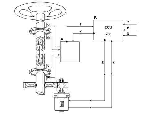
The power assistance together with that of the driver's, depends on the following parameters:
- force applied by the driver,
- vehicle speed,
- steering wheel angular position,
- steering wheel angular speed,
- level of assistance selected (City or Normal)
In all operating conditions the system:
- keeps the effort required for steering below a certain level and dependent on the level of assistance selected (City - Normal)
- ensures the correct return to the centre of the steering wheel during realignment (active return);
- ensures the damping of steering wheel vibrations during return to the centre (active damping).
Control strategies
The power assistance is the result of the following components:
- one main component, a function of the force applied by the driver and the assistance level selected (City or Normal);
- two components that produce 'Active damping' and 'Active return' functions of the steering speed (and the force applied by the driver) and the steering angle, respectively;
- a futher component that has the function of inertia compensation.