3363549 - 1004E20 ENGINE - DISMANTLE AND REASSEMBLE FOLLOWING OPERATION 1004E10 - WASH AND CHECK DISMANTLED PARTS - REFIT CYLINDER HEAD AND OIL SUMP - DOES NOT INCLUDE REPAIRS TO CYLINDER HEAD AND AUXILIARY UNIT


| Description | Code | |
|---|---|---|
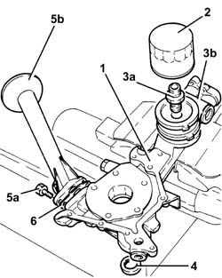
| 1 | Flange | 1.820.618.000 |

| Description | Code | |
|---|---|---|
| - | Flange | 1.820.618.000 |
| Measurement | Value | ||
|---|---|---|---|
| 1 | End float (mm) | 0.049 - 0.211 |


| Measurement | Value | ||
|---|---|---|---|
| - | Cylinder head support surface flatness (mm) | < 0.1 |
| Measurement | Value | ||
|---|---|---|---|
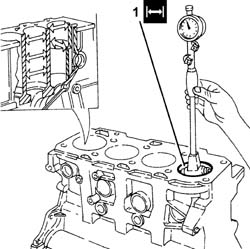
| 1 | Cylinder liner diameter (mm) | Category A | 82.000 - 82.010 |
| Category B | 82.010 - 82.020 | ||
| Category C | 82.020 - 82.030 | ||
| Measurement | Value | ||
|---|---|---|---|
| - | Cylinder liner taper (mm) | < 0.005 |
| Measurement | Value | ||
|---|---|---|---|
| - | Cylinder liner ovality (mm) | < 0.05 |
| In the case of reaming, all the bores must have the same oversize. |
| Measurement | Value | ||
|---|---|---|---|
| - | Cylinder liner oversize (mm) | 0.1 |
| The bearing caps have progressively numbered references (from zero to four starting from the front of the engine) which define the fitting position. |

| Fastening | Component | Ø | Value(daNm) | |
|---|---|---|---|---|
| 1a | Bolt | - | - | 2.5 + 100° |
| Description | Code | |
|---|---|---|
| 1b | Torque wrench | 1.860.942.000 |
| Measurement | Value | ||
|---|---|---|---|
| 2 | Main journal seat diameter (mm) | 63.705 ÷ 63.718 |

| Measurement | Value | ||
|---|---|---|---|
| - | Main journal diameter (mm) | Category A | 59.994 ÷ 60.000 |
| Category B | 59.988 ÷ 59.994 | ||
| Category C | 59.982 ÷ 59.988 | ||
| Measurement | Value | ||
|---|---|---|---|
| - | Main journal diameter undersize (mm) | 0.127 |
| Crankpin undersizes higher than the value mentioned will adversely affect the structural resistance of the crankshaft (following contact between the tool and rolled connectors). As far as the above is concerned, if the regrinding requires undersizes greater than 0.127 mm, then the crankshaft must be replaced and a new one ordered from the Parts Dept. The half-bearings used for undersizes of more than 0.127 mm should not be ordered from the Parts Dept. (even if the number is still quoted). |
| Measurement | Value | ||
|---|---|---|---|
| - | Crankpin diameter (mm) | Category A | 50.799 ÷ 50.805 |
| Category B | 50.793 ÷ 50.799 | ||
| Category C | 50.787 ÷ 50.793 | ||
| Measurement | Value | ||
|---|---|---|---|
| - | Crankpin undersize (mm) | 0.127 |
| Crankpin undersizes higher than the value mentioned will adversely affect the structural resistance of the crankshaft (following contact between the tool and rolled connectors). As far as the above is concerned, if the regrinding requires undersizes greater than 0.127 mm, then the crankshaft must be replaced and a new one ordered from the Parts Dept. The half-bearings used for undersizes of more than 0.127 mm should not be ordered from the Parts Dept. (even if the number is still quoted). |
| If the crankshaft has been ground, fit new oversize half-bearings to restore the initial tolerance conditions. |
| Check one journal at a time, without rotating the crankshaft. |

| The bearing caps have progressively numbered references (from zero to four starting from the front of the engine) which define the fitting position. |

| Fastening | Component | Ø | Value(daNm) | |
|---|---|---|---|---|
| 1a | Bolt | - | - | 2.5 + 100° |
| Description | Code | |
|---|---|---|
| 1b | Torque wrench | 1.860.942.000 |

| Measurement | Value | ||
|---|---|---|---|
| 1b | Clearance between main bearings - crankshaft main journals (mm) | 0.011 ÷ 0.071 |
| If the figure measured is outside of the tolerance, replace the half-bearings with ones of the correct size and category. |

| Measurement | Value | ||
|---|---|---|---|
| - | Inner diameter (mm) | 26.006 ÷ 26.014 |
| Measurement | Value | ||
|---|---|---|---|
| - | Piston bush internal diameter (mm) | 25.999 - 26.004 |
| Measurement | Value | ||
|---|---|---|---|
| - | Outer diameter (mm) | 25.982 ÷ 25.987 |
| Measurement | Value | ||
|---|---|---|---|
| - | Gap (mm) | 1st sealing ring | 0.20 ÷ 0.35 |
| 2nd sealing ring | - | ||
| Measurement | Value | ||
|---|---|---|---|
| - | Gap (mm) | Oil scaper ring | 0.25 - 0.50 |
| Measurement | Value | ||
|---|---|---|---|
| - | Outer diameter (mm) | Category A | 81.920 ÷ 81.930 |
| Category B | 81.930 ÷ 81.940 | ||
| Category C | 81.940 ÷ 81.950 | ||
| Measure perpendicular to the gudgeon pin axis, 9 mm from the lower edge of the skirt. |
| Measurement | Value | ||
|---|---|---|---|
| 1a | Backlash, 2nd ring (mm) | 0.050 ÷ 0.090 |
| Measurement | Value | ||
|---|---|---|---|
| - | End float (mm) | 0.030 ÷ 0.070 |

| Fastening | Component | Ø | Value(daNm) | |
|---|---|---|---|---|
| 1c | Bolt | - | - | 2.5 + 60° |
| Description | Code | |
|---|---|---|
| - | Torque wrench | 1.860.942.000 |
| Measurement | Value | ||
|---|---|---|---|
| 2 | Big end diameter (mm) | 53.897 - 53.909 |

| Description | Code | |
|---|---|---|
| - | Brackets | 1.861.001.139 |
| The crankshaft supplied by the Parts Dept. comes without half-bearings and the main journals and crankpins are the "normal" size; the half-bearings to be fitted must therefore be selected identifying the class of each main journal and crankpin for the new crankshaft. |
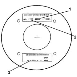
| Only use the codes that relate to the key, all other codes on the flywheel should not be used. |
| The bearing caps have progressively numbered references (from zero to four starting from the front of the engine) which define the fitting position. |

| Fastening | Component | Ø | Value(daNm) | |
|---|---|---|---|---|
| 1a | Bolt | - | - | 2.5 + 100° |
| Description | Code | |
|---|---|---|
| 1b | Torque wrench | 1.860.942.000 |

| Description | Code | |
|---|---|---|
| 1 | Flange | 1.820.618.000 |

| For the selection of the connecting rod half-bearings, follow the procedure described previously for the main journal half-bearings. |
| The piston-connecting rod assemblies should be fitted in the cylinder block/crankcase so that the drain on the piston skirt is aligned with the oil jet on the engine block. |


| Fit the connecting rods so that the number stamped on each rod faces toward the same side as the number stamped on the big end (inlet side). |
| Fastening | Component | Ø | Value(daNm) | |
|---|---|---|---|---|
| 1a | Bolt | - | - | 2.5 + 100° |
| Description | Code | |
|---|---|---|
| 1b | Torque wrench | 1.860.942.000 |