3363555 - 1016E10 SINGLE CYLINDER HEAD, REMOVED - OVERHAUL
| Description | Code | |
|---|---|---|
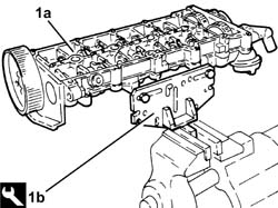
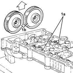
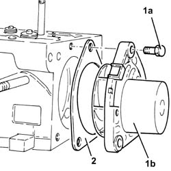
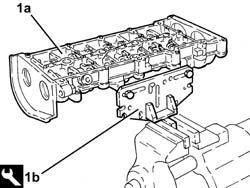
| 1b | Support | 1.860.470.001 |
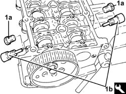
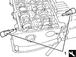
| Check that the tools are correctly fitted in the housings in the camshafts. |
| Description | Code | |
|---|---|---|
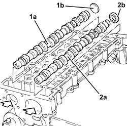
| 1b | Templates | 1.870.896.900 |
| Description | Code | |
|---|---|---|
| - | Templates | 1.870.896.900 |
| Description | Code | |
|---|---|---|
| 1b | Support | 1.860.470.001 |
| Description | Code | |
|---|---|---|
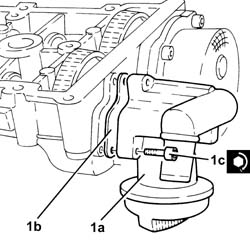
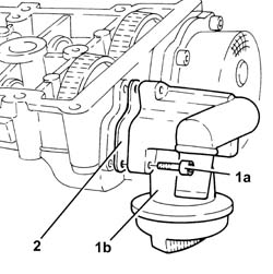
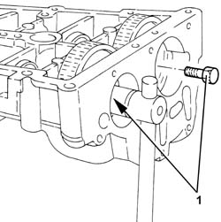
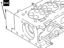
| 1 | Stand | 1.860.804.001 |
| Description | Code | |
|---|---|---|
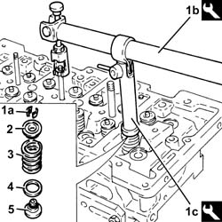
| 1b | Lever | 1.860.644.001 |
| Description | Code | |
|---|---|---|
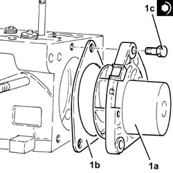
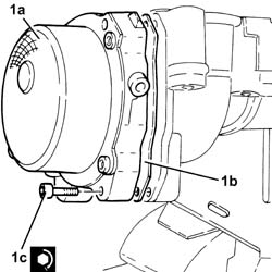
| 1c | Chamber | 1.870.890.000 |
| Description | Code | |
|---|---|---|
| - | Stand | 1.860.804.001 |
| Description | Code | |
|---|---|---|
| - | Support | 1.860.470.001 |
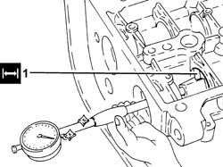
| Measurement | Value | ||
|---|---|---|---|
| - | Lower plane planarity (mm) | 0.1 ± 0.05 |
| Measurement | Value | ||
|---|---|---|---|
| - | Minimum permitted height (mm) | 107.0 ± 0.05 |
| Measurement | Value | ||
|---|---|---|---|
| - | Stem diameter (mm) | Inlet | 5.982 ÷ 6.000 |
| Exhaust | 5.972 ÷ 5.990 | ||
| Measurement | Value | ||
|---|---|---|---|
| - | Free length (mm) | 43.1 |
| Measurement | Value | ||
|---|---|---|---|
| - | Length (mm) | 34.0 | |
| Under a load of (daN) | 20.17 ÷ 21.42 | ||
| Measurement | Value | ||
|---|---|---|---|
| - | Length (mm) | 24.5 | |
| Under a load of (daN) | 42.82 ÷ 45.47 | ||
| Measurement | Value | ||
|---|---|---|---|
| - | Journal diameter (mm) | First journal | 43.600 ÷ 43.615 |
| Fourth journal | 43.000 ÷ 43.015 | ||
| Fifth journal | 30.000 ÷ 30.015 | ||
| Second journal | 43.400 ÷ 43.415 | ||
| Third journal | 43.200 ÷ 43.215 | ||
| Measurement | Value | ||
|---|---|---|---|
| - | Nominal cam height (mm) | Inlet | 8.0 |
| Exhaust | 8.0 | ||
| Measurement | Value | ||
|---|---|---|---|
| - | Bearing diameter (mm) | First bearing | 43.646 ÷ 43.671 |
| Fourth bearing | 43.046 ÷ 43.071 | ||
| Fifth bearing | 30.045 ÷ 30.070 | ||
| Second bearing | 43.446 ÷ 43.471 | ||
| Third bearing | 43.246 ÷ 43.271 | ||
| Measurement | Value | ||
|---|---|---|---|
| - | Outer diameter (mm) | Inlet | 29.489 ÷ 29.514 |
| Exhaust | 27.491 ÷ 27.512 | ||
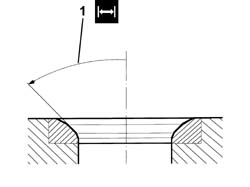
| Measurement | Value | ||
|---|---|---|---|
| - | Contact band angle with inlet valve () | 45° ± 20'' |
| Description | Code | |
|---|---|---|
| - | Support | 1.860.470.001 |
| Description | Code | |
|---|---|---|
| - | Stand | 1.860.804.001 |
| Description | Code | |
|---|---|---|
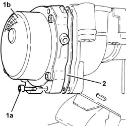
| 1b | Fitting tool | 1.870.897.100 |
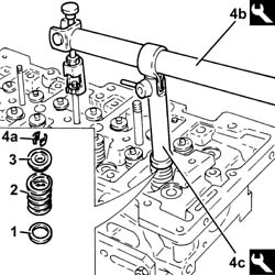
| Description | Code | |
|---|---|---|
| 4b | Lever | 1.860.644.001 |
| Description | Code | |
|---|---|---|
| 4c | Chamber | 1.870.890.000 |
| Description | Code | |
|---|---|---|
| - | Stand | 1.860.804.001 |
| Fastening | Component | Ø | Value(daNm) | |
|---|---|---|---|---|
| 1c | Bolt | - | - | 2.5 |
| Fastening | Component | Ø | Value(daNm) | |
|---|---|---|---|---|
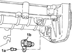
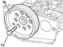
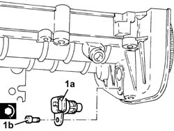
| 1b | Bolt | - | - | 0.9 |
| Description | Code | |
|---|---|---|
| - | Support | 1.860.470.001 |
| Description | Code | |
|---|---|---|
| 1b | Support | 1.860.470.001 |
| Check that the tools are correctly fitted in the housings in the camshafts. |
| Description | Code | |
|---|---|---|
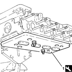
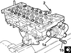
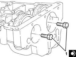
| 1 | Templates | 1.870.896.900 |
| Fastening | Component | Ø | Value(daNm) | |
|---|---|---|---|---|
| 1 | Bolt | - | - | 30 + 40° |
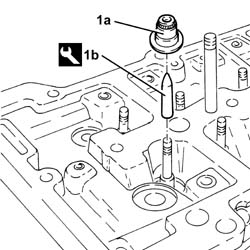
| Description | Code | |
|---|---|---|
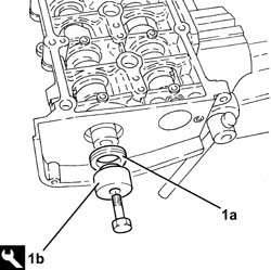
| 1b | Fitting tool | 1.870.896.800 |
| Fastening | Component | Ø | Value(daNm) | |
|---|---|---|---|---|
| 1b | Bolt | - | - | 0.9 |
| Fastening | Component | Ø | Value(daNm) | |
|---|---|---|---|---|
| 1c | Bolt | - | - | 0.5 + 50° |
| Fastening | Component | Ø | Value(daNm) | |
|---|---|---|---|---|
| 1c | - | - | - | - |