3362384 - 1004B12 POWER UNIT WITH MANUAL GEARBOX - R+R FOR VERSIONS WITH A/C

| Description | Connector | |
|---|---|---|
| 1 | Right headlamp | F11 |
| Description | Connector | |
|---|---|---|
| 1 | Left headlamp | F10 |

| Description | Connector | |
|---|---|---|
| 1 | Air Bag front sensor | K39 |
| Description | Connector | |
|---|---|---|
| 2 | Engine fan adjustment resistance | O10 |
| Description | Connector | |
|---|---|---|
| 3 | FRONT ELECTRICALLY OPERATED WINDOW MECH | N11 |

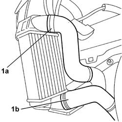
| To disconnect the pipe from the radiator, press the spring manually and release the rapid connector for the pipe from the retainer on the radiator. |

| Description | Connector | |
|---|---|---|
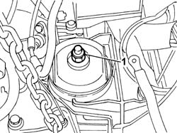
| 1 | Horn | P5 |

| The engine oil used contains substances that are harmful to the environment. Place these substances in containers designed for oil collection and disposal. |

| Collect the engine oil that comes out in a suitable container. |

| Description | Connector | |
|---|---|---|
| 2 | Linear sensor | See K039 FRONT AIR BAG SENSOR |

| Description | Connector | |
|---|---|---|
| 1 | Air flow meter | See K41 AIR FLOW METER |

| Description | Connector | |
|---|---|---|
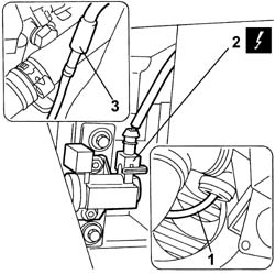
| 2 | Turbine variable geometry control solenoid | L36 |


| Description | Connector | |
|---|---|---|
| 1 | Heater plugs control unit | M15 |


| Description | Connector | |
|---|---|---|
| 1b | Battery earth | C1 |


| Description | Connector | |
|---|---|---|
| 3 | Fuel temperature sensor | K81 |
| Description | Connector | |
|---|---|---|
| 3 | Diesel pre-heating resistance | O20 |
| Description | Connector | |
|---|---|---|
| - | Water in diesel filter sensor | K31 |


| Description | Code | |
|---|---|---|
| 1 | Balance | 1.871.001.700 |


| Take the greatest care not to damage parts fitted to the vehicle during the removal of the engine. |
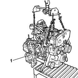
| Take the greatest care not to damage parts fitted to the vehicle during engine installation. |
| Fastening | Component | dia | Value(daNm) | |
|---|---|---|---|---|
| - | Nut | GEARBOX SIDE RUBBER MOUNT | M12 X 1.25 | 10.5 |
| Fastening | Component | dia | Value(daNm) | |
|---|---|---|---|---|
| - | Nut | RIGID ENGINE MOUNT, TIMING SIDE | M12 X 1.25 | (Engine side) 7.5 |
| Description | Code | |
|---|---|---|
| - | Balance | 1.871.001.700 |
| Description | Connector | |
|---|---|---|
| - | Water in diesel filter sensor | K31 |
| Fastening | Component | dia | Value(daNm) | |
|---|---|---|---|---|
| - | Bolt | FUEL FILTER | M8 | (Bodyshell) 2.5 |
| Description | Connector | |
|---|---|---|
| - | Fuel temperature sensor | K81 |
| Description | Connector | |
|---|---|---|
| - | Diesel pre-heating resistance | O20 |
| Fastening | Component | dia | Value(daNm) | |
|---|---|---|---|---|
| - | Nut | LOWER LINK ON GEARBOX | M12 X 1.25 | 7.5 |
| Fastening | Component | dia | Value(daNm) | |
|---|---|---|---|---|
| - | Nut | LOWER ROD ON ENGINE | M12 X 1.25 | 7.5 |
| Fastening | Component | dia | Value(daNm) | |
|---|---|---|---|---|
| - | Bolt | LOWER LINK ON GEARBOX | M12 X 1.25 | 13.5 |
| Fastening | Component | dia | Value(daNm) | |
|---|---|---|---|---|
| - | Bolt | LOWER ROD ON ENGINE | M12 X 1.25 | 13.5 |
| Fastening | Component | dia | Value(daNm) | |
|---|---|---|---|---|
| - | Nut | EXHAUST PIPE TO ENGINE | M8 | (Catalyzer) 2.5 |
| Fastening | Component | dia | Value(daNm) | |
|---|---|---|---|---|
| - | Bolt | EXHAUST PIPE TO ENGINE | M8 | (Catalytic preconverter) 2.5 |
| Fastening | Component | dia | Value(daNm) | |
|---|---|---|---|---|
| - | Bolt | DRIVESHAFT COMPLETE WITH JOINTS | M6 | 1 |
| Fastening | Component | dia | Value(daNm) | |
|---|---|---|---|---|
| - | Nut | FRONT SHOCK ABSORBERS (S.M.) | M10 X 1.25 | (Steering knuckle) 7 |
| Description | Connector | |
|---|---|---|
| - | Battery earth | C1 |
| Description | Connector | |
|---|---|---|
| - | Heater plugs control unit | M15 |
| The bolts securing the front end to the struts should be tightened to a torque of 3 daNm |
| Description | Connector | |
|---|---|---|
| - |
| ... DATA ERROR - CROPPED TEXT | Ошибка данных - Текст обрезан ... |
|---|