3362398 - 1016B10 SINGLE CAMSHAFT HOUSING - REPLACE GASKET
| Description | Connector | |
|---|---|---|
| - | Battery | A1B |

| Description | Connector | |
|---|---|---|
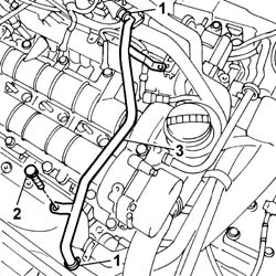
| 1 | Injector | N70 |
| Description | Connector | |
|---|---|---|
| 2 | Timing sensor | K47 |
| Description | Connector | |
|---|---|---|
| 3 | Air conditioning compressor engagement electro-magnet | L20 |

| Use new pipes from the fuel manifold to the injectors when refitting. |

| If the injectors are being reused, mark the cylinder to which they belong so that they can be correctly refitted.If a new injector/new inectors are fitted:- determine the identification code stamped on the top surface;- check, using an Examiner, the the new injector(s) is (are) recognized by the engine management control unit. |
| Begin removal starting from the injector for cylinder 1 and proceed to the injectors for cylinders 2, 3 and 4. |
| Description | Code | |
|---|---|---|
| 2b | Extractor | 1.870.897.300 |

| Use a new pipe from the pressure pump to the fuel manifold when refitting. |

| Description | Connector | |
|---|---|---|
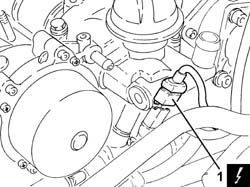
| 1 | Fuel pressure sensor | K83 |


| Description | Connector | |
|---|---|---|
| 1 | Engine temperature sending unit | K36 |


| Check that the tools are correctly fitted in the housings in the camshafts. |
| Description | Code | |
|---|---|---|
| 1b | Templates | 1.870.986.900 |

| Fastening | Component | dia | Value(daNm) | |
|---|---|---|---|---|
| 1b | Bolt | CYLINDER HEAD EXTENSION | M8 | (Cylinder head) 2.5 |

| The crankshaft must be rotated, using small movements, to allow the locating dowel to be fitted on the timing drive pulley. |
| Description | Code | |
|---|---|---|
| 2a | Template | 1.860.905.000 |
| Description | Code | |
|---|---|---|
| 2b | Calibrated screw | 1.860.905.010 |

| Fastening | Component | dia | Value(daNm) | |
|---|---|---|---|---|
| 3c | Nut | FIXED TENSIONER | M8 | 2..5 |
| Fastening | Component | dia | Value(daNm) | |
|---|---|---|---|---|
| 3 | Bolt | TIMING DRIVEN PULLIES | M12 | 12 |

| Description | Code | |
|---|---|---|
| - | Templates | 1.870.986.900 |
| Description | Code | |
|---|---|---|
| - | Template | 1.860.905.000 |
| Description | Code | |
|---|---|---|
| - | Calibrated screw | 1.860.905.010 |
| nly fit the exhaust side camshaft template because the intake side template seat is not accessible. |
| Fastening | Component | dia | Value(daNm) | |
|---|---|---|---|---|
| - | Bolt | FRONT COVER CRANKSHAFT | M6 | 0.9 |
| Description | Connector | |
|---|---|---|
| - | Engine temperature sending unit | K36 |
| Fastening | Component | dia | Value(daNm) | |
|---|---|---|---|---|
| - | Bolt | VACUUM PUMP FOR BRAKES | M6 | 0.5 + 50° |
| Fastening | Component | dia | Value(daNm) | |
|---|---|---|---|---|
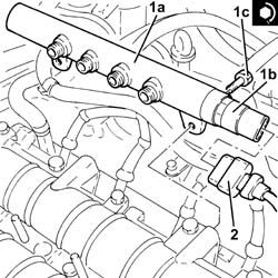
| 1c | Bolt | INJECTOR FUEL MANIFOLD (DIESEL) | M8 | 2.5 |
| Description | Connector | |
|---|---|---|
| 2 | Fuel pressure sensor | K83 |
| Fastening | Component | dia | Value(daNm) | |
|---|---|---|---|---|
| 2 | Connector | PRESSURE PUMP LINE TO FUEL MANIFOLD | M14 X 1.5 | (pump side) 2.3 |
| Fastening | Component | dia | Value(daNm) | |
|---|---|---|---|---|
| 3 | Connector | PRESSURE PUMP LINE TO FUEL MANIFOLD | M14 X 1.5 | (Manifold side) 2.3 |

| Refit starting from the injector for cylinder 4 and proceed to the injectors for cylinders 3, 2 and 1.. |
| Fastening | Component | dia | Value(daNm) | |
|---|---|---|---|---|
| 1b | Nut | INJECTORS(DIESEL) | M8 X 1.25 | 2.5 |

| Fastening | Component | dia | Value(daNm) | |
|---|---|---|---|---|
| - | Connector | PIPE FUEL MANIFOLD TO INJECTORS | M12 x 1.5 | (Injector side) 2.3 |
| Fastening | Component | dia | Value(daNm) | |
|---|---|---|---|---|
| - | Connector | PIPE FUEL MANIFOLD TO INJECTORS | M12 x 1.5 | (Manifold side) 2.3 |
| Clean the threaded pipe seats on the manifold and injectors with heptane. |
| Description | Connector | |
|---|---|---|
| - | Injector | N70 |
| Description | Connector | |
|---|---|---|
| - | Timing sensor | K47 |
| Description | Connector | |
|---|---|---|
| - | Heater plug | A40 |
| Description | Connector | |
|---|---|---|
| - | Air conditioning compressor engagement electro-magnet | L20 |