3362546 - 1016C10 SINGLE CYLINDER HEAD - R.R. AND REPLACE GASKET
| Description | Connector | |
|---|---|---|
| Battery | See A001 BATTERY |
| Collect the coolant that comes out in a suitable container. |

| Arrange the hydraulic tappets on a surface free of impurities and also mark their positions on removal so that they can be refitted in the correct position. |


| Description | Connector | |
|---|---|---|
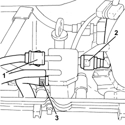
| 1 | EGR solenoid valve | See L030 EGR SOLENOID |
| Description | Connector | |
|---|---|---|
| 2 | Air pressure - temperature sensor | See K044 AIR PRESSURE - TEMPERATURE SENSOR |
| Description | Connector | |
|---|---|---|
| 3 | Turbine variable geometry control solenoid | See L036 TURBINE VARIABLE GEOMETRY CONTROL SOLENOID VALVE |
| Description | Connector | |
|---|---|---|
| 4 | Fuel pressure regulator | See N077 FUEL PRESSURE REGULATOR |


| over the cylinder liners/bores and pistons to prevent the penetration of impurities or foreign bodies. |
| Position the first cylinder at T.D.C.; rotate the crankshaft a further two teeth of the toothed timing drive pulley to lower the pistons thereby preventing any interference with the valves whilst fitting the cylinder head. |
| Value daNm | Fastening | Component | dia | |
|---|---|---|---|---|
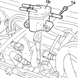
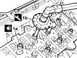
| 1a | 2+6.5+90°+90°+90° | Bolt | Cylinder head | M12 |
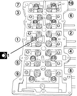
| The figure of 2 daNm in the table below is a tightening value for all the bolts following the order illustrated in the diagram. |
| Description | Code | Function | |
|---|---|---|---|
| 1b | Torque wrench | Tightening cylinder head bolts to cylinder block | 1.860.942.000 |
| Follow the order shown in the previous figure for each tightening sequence. |
| Value daNm | Fastening | Component | dia | |
|---|---|---|---|---|
| - | 2.5 | Bolt | Cylinder head | M8 |
| Value daNm | Fastening | Component | dia | |
|---|---|---|---|---|
| - | 2.5 | Nuts | Exhaust manifold | M8 |
| Value daNm | Fastening | Component | dia | |
|---|---|---|---|---|
| - | 2.5 | Bolt | Engine oil return pipe | M8 |
| Value daNm | Fastening | Component | dia | |
|---|---|---|---|---|
| - | 1.5 | Bolt | Engine oil delivery pipe | M12 |
| Value daNm | Fastening | Component | dia | |
|---|---|---|---|---|
| - | 2.5 | Nuts | Preconverter bracket | M8 (oil sump) |
| Value daNm | Fastening | Component | dia | |
|---|---|---|---|---|
| - | 2.5 | Nuts | Engine/manifold exhaust pipe | M8 |
| Value daNm | Fastening | Component | dia | |
|---|---|---|---|---|
| - | 2.5 | Nuts | Catalytic preconverter | M8 (support bracket) |
| Value daNm | Fastening | Component | dia | |
|---|---|---|---|---|
| - | 0.9 | Bolt | Exhaust manifold heat shield | M6 (support bracket) |
| Value daNm | Fastening | Component | dia | |
|---|---|---|---|---|
| - | 0.9 | Nuts | Exhaust manifold heat shield | M6 |
| Value daNm | Fastening | Component | dia | |
|---|---|---|---|---|
| - | 0.9 | Bolt | Engine coolant pump rigid inlet pipe | M6 |
| Description | Connector | |
|---|---|---|
| - | Fuel pressure regulator | See N077 FUEL PRESSURE REGULATOR |
| Description | Connector | |
|---|---|---|
| - | Turbine variable geometry control solenoid | See L036 TURBINE VARIABLE GEOMETRY CONTROL SOLENOID VALVE |
| Description | Connector | |
|---|---|---|
| - | Air pressure - temperature sensor | See K044 AIR PRESSURE - TEMPERATURE SENSOR |
| Description | Connector | |
|---|---|---|
| - | Turbine variable geometry control solenoid | See L036 TURBINE VARIABLE GEOMETRY CONTROL SOLENOID VALVE |