3363369 - 7040A97 facia trim support beam - r r

Removing ( Refitting ) - 5040A10 Air conditioning refrigerant CIRCUIT - Draining and Refilling  - 5530B56  BATTERY DRIP TRAY COVER - R.R.- 5530B10 battery - r+r  - 5530B52  Battery DRIP TRAY/SUPPORT - R.R. - 1016A40  ignition coil cover on cylinder head- r+r - 1056B82  injection/ignition system e.c.u. (one) - r + r - 1048A31  RIGID PIPE between air filter and intake manifold - R.R. - 1056B15  throttle body intergral with mds - r r - 1056B87  ignition/injection system control unit mount - r r - 1048A23  cold air intake - r r1. Disconnect the flow meter electrical connector.

NameConnector
1Air flow meter  K41 
Raise the car on a lift. - 7055B54  under-engine guard - r r - 7055B42  Additional FRONT WHEEL ARCH (one), left or right - R.R. (left side) 1. Remove the air filter casing.
Lower the car with the lift.1. Disconnect the lower hose from the radiator and drain the engine cooling system.
1. Disconnect the electrical connector for the coupling for the engine wiring (1a), the water temperature sensor (1b) and the earth on the engine (1c) and move it aside.

NameConnector
1aFront/engine connection  D4A 

NameConnector
1bEngine temperature sender unit  K36 

NameConnector
1cEarth on engine  C40 
Release the heater water supply and return pipes from the thermostat and from the water pump manifold, respectively, acting on the retaining bands. Raise the car on a lift.Position a suitable container for collecting the coolant fluid.1. Open the band securing the heater water supply pipe to the heater inlet pipe and move it aside.2. Open the band securing the heater water return pipe and disconnect the pipe and move it aside.
1. Disconnect the pipes (1a) from the expansion valve (1b).
 - 7040L33  ARMREST ON TUNNEL COVER WITH ODDMENTS POCKET - R.R. - 3380A46  handbrake lever protective boot - r r - 7040L37  gear lever plate - r r - 7040A65  passenger compartment box lock , one , r r (left and right sides)  - 7065C42  ashtray (one) r+r - 5010C32  air outlet on panel trim for rear seats - r r - 7040L70  TUNNEL COVER REAR TRIM - R.R. - 7040L20  tunnel trim - r r - 7040A45  facia rh side cover - r r - 7040A31  flap assembly - r r - 5570T80  car radio unit - r+r - 7040A25  central facia trim - r r- 5570T10 car radio support - r+r - includes contact repair and supply circuit check  - 5040D15  control unit with automatic duel zone air conditioner knobs and buttons r r - 5550C14  hazard warning light switch - r+r - 5580C18  air bag module - r+r- 4110A16 steering wheel - r r for replacement or checks for versions with airbag and manual gearbox with hydraulic selection  - 7040A26  steering column trim - r+r - 5580C12  clock spring for air bag module on steering wheel r r - 5550A12  complete stalk unit - r+r for versions with air bag - 5560B10  analogue control panel - r+r - 7040A45  facia rh side cover - r r - 7040A44  facia lh side cover - r r - 7040A82  EXTERIOR LIGHTS SWITCH PANEL, INSTRUMENT PANEL LIGHT AND MULTIFUNCTION DISPLAY DIMMER - R.R . - 5010D56  solar sensor - r r after checking electrical system - 7040A07  upper compartment on facia - r r - 5580C22  AIR BAG MODULE - Passenger side - R.R. - 7040A31  flap assembly - r r - 7040A10  instrument facia trim - r+r - 4110D20  steering electrical control device - r r - 5505A36  BODY COMPUTER/MAIN JUNCTION UNIT ASSEMBLY - DISMANTLING AT THE BENCH - 7040A89  REINFORCEMENT BRACKET BETWEEN DASHBOARD SUPPORTING CROSSMEMBER AND BODYSHELL - R.R.1. Break the rivets (1a), using the special equipment, and remove the tunnel cover mounting brackets (1b).2. Release and remove the connectors for the climate control system lower hoses.
1. Disconnect the rigid pipe for draining the climate control system condensation.
1. Undo the bolts on both sides fixing the crossmember to the bodyshell.2. Undo the upper fixing bolts (2a) and remove the crossmember (2b) from its housing.
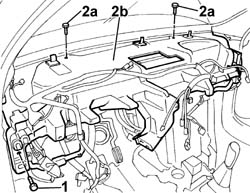
In order to undo the upper fixing bolts a special spanner has to be modified leaving the shorter end of the spanner less than 20 mm high.
Dismantle the crossmember with the help of a second operator.
1. At the bench, undo the fixing bolts (1a) and separate the climate control unit (1b) from the crossmember (1c).2. Release the electrical wiring on the crossmember from the retaining bands and remove it.
Refitting ( Removing ) Secure the dashboard electrical wiring to the retaining springs on the crossmember.Fit the climate control unit on the crossmember and secure it using the bolts.Fit the crossmember in position and tighten the bolts fixing it to the bodyshell to torque.

FasteningComponentØValue(daNm)
-BoltFACIA TRIMMOUNT BEAMM8(Side) 3.5
Connect the climate control system rigid condensation drainage pipe.Fit the connectors for the climate control unit lower hoses in position.Fit the tunnel cover mounting brackets and secure them to the passenger compartment floor using new rivets. - 7040A89  REINFORCEMENT BRACKET BETWEEN DASHBOARD SUPPORTING CROSSMEMBER AND BODYSHELL - R.R. - 5505A36  BODY COMPUTER/MAIN JUNCTION UNIT ASSEMBLY - DISMANTLING AT THE BENCH - 4110D20  steering electrical control device - r r - 7040A10  instrument facia trim - r+r - 7040A31  flap assembly - r r - 5580C22  AIR BAG MODULE - Passenger side - R.R. - 7040A07  upper compartment on facia - r r - 5010D56  solar sensor - r r after checking electrical system - 7040A82  EXTERIOR LIGHTS SWITCH PANEL, INSTRUMENT PANEL LIGHT AND MULTIFUNCTION DISPLAY DIMMER - R.R . - 7040A44  facia lh side cover - r r - 7040A45  facia rh side cover - r r - 5560B10  analogue control panel - r+r - 5550A12  complete stalk unit - r+r for versions with air bag - 5580C12  clock spring for air bag module on steering wheel r r - 7040A26  steering column trim - r+r- 4110A16 steering wheel - r r for replacement or checks for versions with airbag and manual gearbox with hydraulic selection  - 5580C18  air bag module - r+r - 5550C14  hazard warning light switch - r+r - 5040D15  control unit with automatic duel zone air conditioner knobs and buttons r r- 5570T10 car radio support - r+r - includes contact repair and supply circuit check  - 7040A25  central facia trim - r r - 5570T80  car radio unit - r+r - 7040A31  flap assembly - r r - 7040A45  facia rh side cover - r r - 7040L20  tunnel trim - r r - 7040L70  TUNNEL COVER REAR TRIM - R.R. - 5010C32  air outlet on panel trim for rear seats - r r - 7065C42  ashtray (one) r+r - 7040A65  passenger compartment box lock , one , r r (left and right sides)  - 7040L37  gear lever plate - r r - 3380A46  handbrake lever protective boot - r r - 7040L33  ARMREST ON TUNNEL COVER WITH ODDMENTS POCKET - R.R.Fasten the pipes to the expansion valve tightening the fixing bolts.Secure the water supply and return pipes, heater side, to the heater using the retaining bands.Lower the car with the lift.Fasten the heater water supply and return pipes to the thermostat and to the water pump manifold, respectively, using the retaining bands.Connect the electrical connector for the coupling for the engine wiring, the water temperature sensor and the earth on the engine and move it aside.

NameConnector
-Front/engine connection  D4A 

NameConnector
-Engine temperature sender unit  K36 

NameConnector
-Earth on engine  C40 
Connect the lower hose to the radiator and top up the level of the coolant in the engine cooling circuit.Raise the car on a lift.Place the air filter casing in its housing. - 7055B42  Additional FRONT WHEEL ARCH (one), left or right - R.R. (left side)  - 7055B54  under-engine guard - r rLower the car with the lift.Connect the flow meter electrical connector.

NameConnector
-Air flow meter  K41 
 - 1048A23  cold air intake - r r - 1056B87  ignition/injection system control unit mount - r r - 1056B15  throttle body intergral with mds - r r - 1048A31  RIGID PIPE between air filter and intake manifold - R.R. - 1056B82  injection/ignition system e.c.u. (one) - r + r - 1016A40  ignition coil cover on cylinder head- r+r - 5530B52  Battery DRIP TRAY/SUPPORT - R.R.- 5530B10 battery - r+r  - 5530B56  BATTERY DRIP TRAY COVER - R.R.- 5040A10 Air conditioning refrigerant CIRCUIT - Draining and Refilling