3363560 - 1024A10 crank shaft - r + r with engine removed - check main and connecting rod bearingand replace if necessary
 | Name | Connector |
|---|---|---|
| 1 | Timing sensor | K47 |
| Name | Connector |
|---|---|---|
| 3 | Injector | N70 |

| Name | Connector |
|---|---|---|
| 2 | Heater plug | A40 |
| Name | Connector |
|---|---|---|
| 3 | Fuel pressure sensor | K83 |
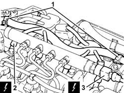


| Use a new pipe from the pressure pump to the fuel manifold when refitting. |
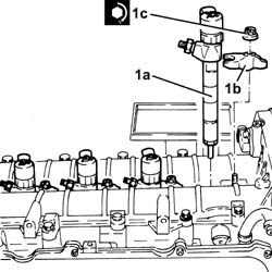
| Use new pipes from from fuel manifold to injectors upon reassembly. |

| Start the removal beginning with the injector for cylinder no. 1 and continuing with the injectors for cylinders 2, 3 and 4. |


 | Name | Country |
|---|---|---|
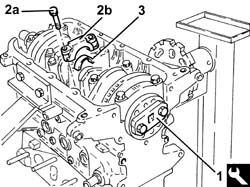
| 1 | Counter-torque | 1.860.846.001 |


| The engine flywheel retaining bolts are treated with a compound to prevent them coming undone they should therefore be replaced whenever they are removed. |
| Name | Country |
|---|---|---|
| 2 | Counter-torque | 1.860.846.001 |


| Name | Country |
|---|---|---|
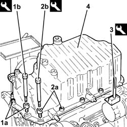
| 1b | Spanner | 1.860.833.001 |
| Name | Country |
|---|---|---|
| 2b | Spanner | 1.860.834.001 |
| Name | Country |
|---|---|---|
| 3 | Blade | 1.870.718.000 |


| Name | Country |
|---|---|---|
| 1 | Flange | 1.820.618.000 |
| Name | Country |
|---|---|---|
| - | Flange | 1.820.618.000 |
 | Measurement | Value | |
|---|---|---|---|
| 1 | End float (mm) | 0.049 - 0.211 |


| Measurement | Value | |
|---|---|---|---|
| - | Half-bearing thickness (mm) | Category B | 1.836 ÷ 1.844 |
| Category C | 1.843 ÷ 1.849 | ||
| Class A | 1.831 ÷ 1.837 | ||
| Measurement | Value | |
|---|---|---|---|
| - | Connecting rod half bearing thickness (mm) | Category B | 1.530 ÷ 1.534 |
| Category C | 1.533 ÷ 1.537 | ||
| Classe A | 1.527 ÷ 1.531 | ||
| The crankshaft is supplied, by the Parts Dept., without the appropriate half-bearings for 'normal' dimension main journals and crank pins; it is therefore necessary to select the main journal half-bearings to be fitted identifying the grade for each main journal and crank pin for the new crankshaft. |

| Only use the codes in the key, all other codes on the flywheel should not be used. |
| The bearing caps have progressive references (from zero to four starting from the front of the engine) which define their fitting position. |

 | Fastening | Component | Ø | Value(daNm) |
|---|---|---|---|---|
| 1a | - | - | - | - |
| Name | Country |
|---|---|---|
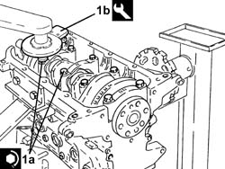
| 1b | Protractor | 1.860.942.000 |
| Name | Country |
|---|---|---|
| 1 | Flange | 1.820.618.000 |
| To select the connecting rod half-bearings, follow the procedure described previously for the main journal half-bearings. |
| The connecting rod caps are fitted so that the number stamped on them is facing the same side as the one stamped on the big end (inlet side). |
| Fastening | Component | Ø | Value(daNm) |
|---|---|---|---|---|
| 2a | - | - | - | - |
| Name | Country |
|---|---|---|
| 2b | Protractor | 1.860.942.000 |

| Name | Country |
|---|---|---|
| - | Flange | 1.820.618.000 |
| Fastening | Component | Ø | Value(daNm) |
|---|---|---|---|---|
| 1c | - | - | - | - |

| Name | Country |
|---|---|---|
| 1b | Fitting tool | 1.821.247.000 |

| Fastening | Component | Ø | Value(daNm) |
|---|---|---|---|---|
| 1b | - | - | - | - |

| Fastening | Component | Ø | Value(daNm) |
|---|---|---|---|---|
| 1b | - | - | - | - |

| Fastening | Component | Ø | Value(daNm) |
|---|---|---|---|---|
| 1b | - | - | - | - |

| Fastening | Component | Ø | Value(daNm) |
|---|---|---|---|---|
| 1b | - | - | - | - |

| Fastening | Component | Ø | Value(daNm) |
|---|---|---|---|---|
| 2a | - | - | - | - |
| Name | Country |
|---|---|---|
| 2b | Spanner | 1.860.833.001 |
| Fastening | Component | Ø | Value(daNm) |
|---|---|---|---|---|
| 3a | - | - | - | - |
| Name | Country |
|---|---|---|
| 3b | Spanner | 1.860.834.001 |

| Name | Country |
|---|---|---|
| 1 | Counter-torque | 1.860.846.001 |
| Fastening | Component | Ø | Value(daNm) |
|---|---|---|---|---|
| 2b | - | - | - | - |
| Name | Country |
|---|---|---|
| - | Protractor | 1.860.942.000 |

| Fastening | Component | Ø | Value(daNm) |
|---|---|---|---|---|
| 1b | - | - | - | - |

| Name | Country |
|---|---|---|
| - | Counter-torque | 1.860.846.001 |
| Check that the tools are correctly inserted in the housings in the camshafts. |
| Name | Country |
|---|---|---|
| 1b | Gauge | 1.870.896.900 |

| Fastening | Component | Ø | Value(daNm) |
|---|---|---|---|---|
| 1b | - | - | - | - |

| To allow the engagement of the locating dowel on the timing drive belt drive pulley in the opening in the tool, rotate the crankshaft using small movements. |
| Name | Country |
|---|---|---|
| 2a | Template | 1.860.905.000 |
| Name | Country |
|---|---|---|
| 2b | Calibrated screw | 1.860.905.010 |

| Fastening | Component | Ø | Value(daNm) |
|---|---|---|---|---|
| 2d | - | - | - | - |

| Fastening | Component | Ø | Value(daNm) |
|---|---|---|---|---|
| - | - | - | - | - |
| Name | Country |
|---|---|---|
| - | Gauge | 1.870.896.900 |
| Remove the exhaust camshaft template, as the inlet camshaft has already been removed. |
| Name | Country |
|---|---|---|
| - | Template | 1.860.905.000 |
| Name | Country |
|---|---|---|
| - | Calibrated screw | 1.860.905.010 |
| Only fit the exhaust camshaft side template because the inlet side one is not accessible. |
| Start the refitting beginning with the injector for cylinder no. 4 and continuing with the injectors for cylinders 3, 2 and 1. |
| Fastening | Component | Ø | Value(daNm) |
|---|---|---|---|---|
| 1c | - | - | - | - |
| Fastening | Component | Ø | Value(daNm) |
|---|---|---|---|---|
| 1c | - | - | - | - |
| Fastening | Component | Ø | Value(daNm) |
|---|---|---|---|---|
| 3 | - | - | - | - |
| Fastening | Component | Ø | Value(daNm) |
|---|---|---|---|---|
| 4 | - | - | - | - |
| Clean the threaded seats for the above-mentioned pipe on the manifold and the injectors using heptane. |
| Fastening | Component | Ø | Value(daNm) |
|---|---|---|---|---|
| 7 | - | - | - | - |
| Fastening | Component | Ø | Value(daNm) |
|---|---|---|---|---|
| 8 | - | - | - | - |
| Clean the threaded seats for the above mentioned pipe on the manifold and the pressure pump using heptane. |

| Fastening | Component | Ø | Value(daNm) |
|---|---|---|---|---|
| 1b | - | - | - | - |
| Fastening | Component | Ø | Value(daNm) |
|---|---|---|---|---|
| 1c | - | - | - | - |

| Fastening | Component | Ø | Value(daNm) |
|---|---|---|---|---|
| 1b | - | - | - | - |
| Name | Country |
|---|---|---|
| - | Counter-torque | 1.860.846.001 |
| Fastening | Component | Ø | Value(daNm) |
|---|---|---|---|---|
| 2b | - | - | - | - |
| Name | Country |
|---|---|---|
| - | Counter-torque | 1.860.846.001 |
