3363561 - 1028H14 PISTON CONNECTING ROD SET - R.R. WITH ENGINE AND CYLINDER HEAD(S) REMOVED
| Description | Code | |
|---|---|---|
| 1 | Counter-torque | 1.860.846.001 |
| The bolts fixing the flywheel have been treated with a special agent; therefore they should be replaced each time they are removed. |
| Description | Code | |
|---|---|---|
| - | Counter-torque | 1.860.846.001 |


| Description | Code | |
|---|---|---|
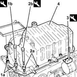
| 1b | Spanner | 1.860.833.001 |
| Description | Code | |
|---|---|---|
| 2b | Spanner | 1.860.834.001 |
| Description | Code | |
|---|---|---|
| 3 | Blade | 1.870.718.000 |

| Description | Code | |
|---|---|---|
| 1 | Flange | 1.820.618.000 |

| For the selection of the connecting rod half-bearings, follow the procedure described previously for the main journal half-bearings. Op. 1004E20 ENGINE - DISMANTLE AND REASSEMBLE FOLLOWING OPERATION 1004E10 - WASH AND CHECK DISMANTLED PARTS - REFIT CYLINDER HEAD AND OIL SUMP - DOES NOT INCLUDE REPAIRS TO CYLINDER HEAD AND AUXILIARY UNIT. |
| The piston-connecting rod assemblies should be fitted in the cylinder block/crankcase so that the drain on the piston skirt is aligned with the oil jet on the engine block. |


| Fit the connecting rods so that the number stamped on each rod faces towardt he same side as the number stamped on the big end (inlet side). |
| Fastening | Component | Ø | Value(daNm) | |
|---|---|---|---|---|
| 1a | Bolt | - | - | 2.5 + 100° |
| Description | Code | |
|---|---|---|
| 1b | Torque wrench | 1.860.942.000 |

| Measurement | Value | ||
|---|---|---|---|
| 1b | Clearance between connecting rod bearings - crankpins (mm) | 0.016 ÷ 0.070 |

| Fit the connecting rods so that the number stamped on each rod faces toward the same side as the number stamped on the big end (inlet side). |
| Fastening | Component | Ø | Value(daNm) | |
|---|---|---|---|---|
| 1a | Bolt | - | - | 2.5 + 60° |
| Description | Code | |
|---|---|---|
| 1b | Torque wrench | 1.860.942.000 |

| Description | Code | |
|---|---|---|
| - | Flange | 1.820.618.000 |
| Fastening | Component | Ø | Value(daNm) | |
|---|---|---|---|---|
| 2a | Bolt | - | - | 2.5 |
| Description | Code | |
|---|---|---|
| 2b | Spanner | 1.860.833.001 |
| Fastening | Component | Ø | Value(daNm) | |
|---|---|---|---|---|
| 3a | Bolt | - | - | 2.5 |
| Description | Code | |
|---|---|---|
| 3b | Spanner | 1.860.834.001 |

| Description | Code | |
|---|---|---|
| 1 | Counter-torque | 1.860.846.001 |
| Fastening | Component | Ø | Value(daNm) | |
|---|---|---|---|---|
| 2b | Bolt | - | - | 16 |
| Description | Code | |
|---|---|---|
| - | Torque wrench | 1.860.942.000 |

| Description | Code | |
|---|---|---|
| - | Counter-torque | 1.860.846.001 |