3363594 - 2110B26 manual gearbox (six speed) with differential - dismantle and rebuild wash and check parts - replace synchronizers and internal parts if necessary
 | Name | Country |
|---|---|---|
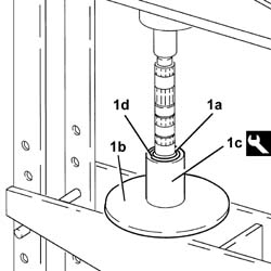
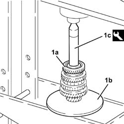
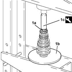
| 1c | Mount | 1.870.644.001 |

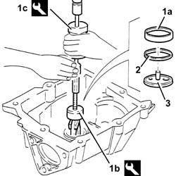
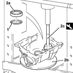
| Two operators are needed for this operation. |
| Name | Country |
|---|---|---|
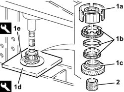
| 1b | Mount | 1.820.146.000 |

| Name | Country |
|---|---|---|
| 1b | Flange | 1.820.229.000 |
| Name | Country |
|---|---|---|
| 1c | Counter weight | 1.821.161.000 |


| The gearbox casing is sealed to the bell housing: release the two parts using a wooden or resin hammer. |

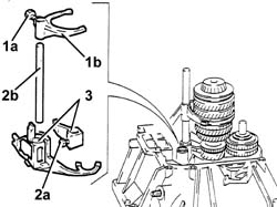
| Keep the units assembled until they are placed on the workbench. |
| The mainshaft cannot be serviced |


| Name | Country |
|---|---|---|
| 1b | Extractor | 1.820.626.000 |
| Name | Country |
|---|---|---|
| 1c | Counter weight | 1.840.206.001 |

| Name | Country |
|---|---|---|
| 1b | Tool for Extracting/Fitting | 1.870.655.000 |
| Name | Country |
|---|---|---|
| 1c | Counter weight | 1.840.206.001 |
| Name | Country |
|---|---|---|
| 1b | Tool for Extracting/Fitting | 1.870.655.000 |
| Name | Country |
|---|---|---|
| 1c | Counter weight | 1.840.206.001 |
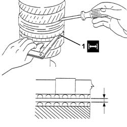
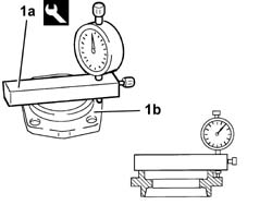
| In order to carry out the measurement, keep the sliding sleeve raised using a screwdriver. |
 | Measurement | Value | |
|---|---|---|---|
| 1 | Gear. teeth clearance and synchronizer ring support. surfaces (mm) | >= 0.8 |
| Name | Country |
|---|---|---|
| 1c | Plate | 1.820.047.002 |
| Name | Country |
|---|---|---|
| 1d | Half-rings | 1.870.675.000 |

| Name | Country |
|---|---|---|
| 1c | Plate | 1.820.047.002 |
| Name | Country |
|---|---|---|
| 1d | Half-rings | 1.870.675.000 |

| Name | Country |
|---|---|---|
| 1c | Plate | 1.820.047.003 |
| Name | Country |
|---|---|---|
| 1d | Half-rings | 1.820.046.000 |

| When refitting, replace the circplip. |

| Name | Country |
|---|---|---|
| 1d | Plate | 1.820.047.003 |
| Name | Country |
|---|---|---|
| 1e | Half-rings | 1.820.046.000 |
| When refitting, replace the circplip. |

| Name | Country |
|---|---|---|
| 1c | Reaction base | 1.870.660.000 |


| Lubricate the bearings with the recommended oil before refitting them. |
 | Type | Component | Name | Qty. |
|---|---|---|---|---|
| - | Oil | MANUAL GEARBOX | TUTELA ZC 75 FF SEMI SYNTH | - |
| Name | Country |
|---|---|---|
| 1c | Tool for Extracting/Fitting | 1.870.658.000 |


| The size of the circlip should be selected from those available as spares (1.975; 2.020; 2.065) according to the value of the housing measured previously. |
| Name | Country |
|---|---|---|
| 1c | Tool for Extracting/Fitting | 1.870.658.000 |


| Name | Country |
|---|---|---|
| 1c | Tool for Extracting/Fitting | 1.870.658.000 |
| Name | Country |
|---|---|---|
| 1c | Tool for Extracting/Fitting | 1.870.658.000 |

| Name | Country |
|---|---|---|
| 1c | Tool for Extracting/Fitting | 1.870.658.000 |

| Name | Country |
|---|---|---|
| 1c | Tool for Extracting/Fitting | 1.870.658.000 |

| Name | Country |
|---|---|---|
| 1c | Fitting tool | 1.870.659.000 |
| 'Permaglide' self-lubricated bushes should not be lubricated under any circumstances because the lubricating oil or grease would mix, over a period of time, with the abrasive material of the bush forming a mixture which would increase the wear of the actual bush.' |

| Name | Country |
|---|---|---|
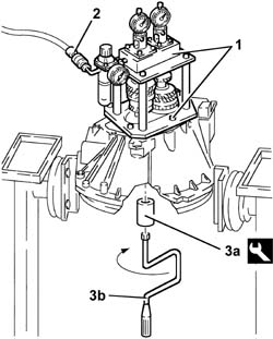
| 1 | Gauges | 1.870.648.000 |

| Name | Country |
|---|---|---|
| 1 | Reference crossmember | 1.870.649.000 |


| Name | Country |
|---|---|---|
| 1a | Gauges | 1.870.648.000 |
| Name | Country |
|---|---|---|
| 1b | Mount | 1.870.647.000 |

| Name | Country |
|---|---|---|
| 1a | Mount | 1.870.647.000 |


| Name | Country |
|---|---|---|
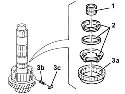
| 3a | Bush | 1.870.652.000 |
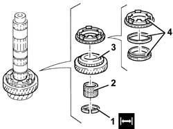
| Below is an example of how to calculate the size of the scraper rings. |


| Name | Country |
|---|---|---|
| 3c | Fitting tool | 1.870.657.000 |

| Name | Country |
|---|---|---|
| 2c | Fitting tool | 1.870.657.000 |

 | Fastening | Component | Ø | Value(daNm) |
|---|---|---|---|---|
| 2b | Bolt | 5thª speed control rod | M8 | 2.1 - 2.6 |
| Fastening | Component | Ø | Value(daNm) |
|---|---|---|---|---|
| 3b | Bolt | 5thª speed selector fork | M8 | 2.1 - 2.6 |

| Type | Component | Name | Qty. |
|---|---|---|---|---|
| - | Sealant | GEARBOX GEAR CASING | Loctite 510 | - |
| Fastening | Component | Ø | Value(daNm) |
|---|---|---|---|---|
| 1b | Bolt | GEARBOX GEAR CASING | M9 | 2.9 - 3.6 |
| Fastening | Component | Ø | Value(daNm) |
|---|---|---|---|---|
| 2 | Bolt | Reverse shaft | M10 | 4.3 - 5.3 |

| Type | Component | Name | Qty. |
|---|---|---|---|---|
| - | Sealant | GEARBOX DIFFERENTIAL MOUNT | Loctite 510 | - |
| Fastening | Component | Ø | Value(daNm) |
|---|---|---|---|---|
| 1b | Bolt | GEARBOX DIFFERENTIAL MOUNT | M10 | 4.3 ÷ 5.3 |
| Fastening | Component | Ø | Value(daNm) |
|---|---|---|---|---|
| 1b | Bolt | GEARBOX DIFFERENTIAL MOUNT | M8 | 2.1 - 2.6 |

| Fastening | Component | Ø | Value(daNm) |
|---|---|---|---|---|
| 1b | Bolt | MAN G/BOX DIFF SEALING FLANGE/S | M8 | 2.1 - 2.6 |

| Name | Country |
|---|---|---|
| 1 | Dial gauge mounting | 1.820.085.000 |

| Name | Country |
|---|---|---|
| 1a | Dial gauge mounting | 1.820.085.000 |
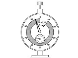
| 0.12 corresponds to the interference for bedding in and the pre-loading of the differential bearings. |
| Fastening | Component | Ø | Value(daNm) |
|---|---|---|---|---|
| 2b | Bolt | MAN G/BOX DIFF SEALING FLANGE/S | M8 | 2.1 - 2.6 |
| The matching surfaces of the main shaft cover and the thrust bearing should be lubricated with Molycote PG 21 type grease. |

| The two fork levers should be lubricated with Molycote PG 21 type grease. |
| 'Permaglide' self-lubricated bushes should not be lubricated under any circumstances because the lubricating oil or grease would mix, over a period of time, with the abrasive material of the bush forming a mixture which would increase the wear of the actual bush.' |
| Two operators are needed for this operation. |
| Name | Country |
|---|---|---|
| - | Mount | 1.820.146.000 |
| Name | Country |
|---|---|---|
| - | Mount | 1.870.644.001 |