3363715 - Introduction - INSTRUMENT PANEL
INSTRUMENT PANEL NODE
SPECIFICATIONS
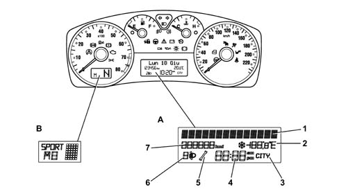
The Instrument Panel Node (NQS) comes in two versions: LOW version with an alphanumeric LCD + a 14 character SEMI DOT - MATRIX HIGH version, with a DOT --MATRIX LCD + two LCDs,On the LOW version there is also a variant for Automatic Transmission with an extra LCD in the rev counter section to display the gear engaged and the gearbox operating mode. There are 12 different variants for the Instrument Panels because each time of instrument (Low, Low CA, and High) are different for the Petrol and Diesel versions and the unit of measurement for the speedometer may be in Km/h or MPH.The High version of the instrument panel has either white graphics or black graphics.The NQS is connected to the B - CAN network and one of its functions is to wake the network up again when the NBC cannot do it (e.g. it is faulty).Low instrument panel
Low Instrument Panel without Selespeed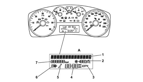
The Low panel comprises 4 analogue indicators:
- electronic speedometer
- electronic rev counter
- engine temperature gauge (with overheating warning light)
- fuel gauge (with reserve warning light)
There is a central alphanumeric LCD to show the following functions / scales:
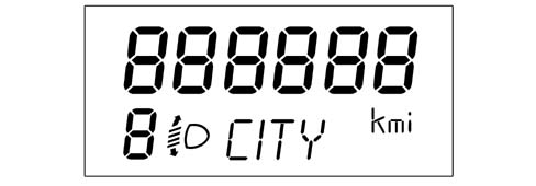
- total mileage
- clock
- outside temperature (and ice danger symbol)
- date
- headlamp alignment correction symbol / indicator
- CITY mode selection symbol / indicator (electric steering)
Still in the centre display, the first line at the top consists of 14 alphanumerical characters where, in additional to displaying the 'dae' in a standard format, the following functions are also displayed (on request or as they occur):
- check stage at key on
- Trip Computer information (general and Trip B)
- warning / service / function activation fault messages
- repetition of the audio / telephone function indications
- vehicle setup menu with setting / adjustment messages
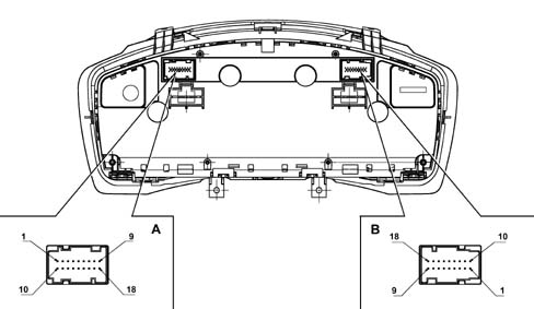
| PIN | FUNCTION |
|---|---|
| 1 | INT from F-37/RUN/+15 |
| 2 | +30 from F-53/batteria |
| 3 | B - CAN A |
| 4 | B - CAN B |
| 5 | Headlamp alignment actuator signal reference |
| 6 | + dipped headlamps from F-13 to control headlamp alignment |
| 7 | Earth |
| 8 | Negative signal from trip computer button on steering column switch unit |
| 9 | Signal from controls on PCS: 'Zero Km', 'Mode -' |
| 10 | I.E. failure/EOBD warning light negative signal from NCM |
| 11 | Signal from PCS 'headlamp up alignment', 'headlamp down alignment' |
| 12 | Dimmed positive control for door switch panel lighting LED |
| 13 | CAB failure warning light negative signal (AIR-BAG) |
| 14 | Passenger Air Bag disabled warning light negative signal |
| 15 | Seat belts not fastened neagive signal |
| 16 | Signal at PCS: 'Mode', 'Mode +', light intensity adjustment |
| 17 | Engine oil level sensor supply |
| 18 | Signal from engine oil level sensor |
| PIN | FUNCTION |
|---|---|
| 1 | Signal from engine oil temperature sender unit |
| 2 | Signal from engine oil pressure sender unit |
| 3 | Spare warning light negative signal |
| 4 | Selespeed buzzer signal |
| 5 | Not connected |
| 6 | Not connected |
| 7 | SCS failure signal |
| 8 | Rear bags disabled warning light negative signal |
| 9 | Not connected |
| 10 | Not connected |
| 11 | Not connected |
| 12 | Not connected |
| 13 | Not connected |
| 14 | Not connected |
| 15 | Not connected |
| 16 | Not connected |
| 17 | Not connected |
| 18 | Not connected |
High instrument panel
High Instrument Panel
The High Instrument Panel consists of 4 analogue indicators:
- electronic speedometer
- electronic rev counter
- engine temperature gauge (with overheating warning light)
- fuel gauge (with reserve warning light)
On the High version there is 1 8 colour passive matrix display (red, green, blue, cornflower blue, magenta, yellow, black and white) for displaying the following functions / scales:
- check stage at key on
- Trip Computer information (general and Trip B)
- outside temperature (and ice warning symbol)
- date
- failure, warning, function activation, service messages and symbols
- repetition of audio, telephone, navigation function indications
- set up menu with setting / adjustment messages
- display of gear engaged and gearbox operating mode
There is 1 LCD for displaying the following functions:
- total mileage
- headlamp alignment symbol / indication
- CITY driving mode selection symbol / indication (electric steering)
| FUNCTIONS | Always present | At key on | At the occurrence | On request | NOTES |
|---|---|---|---|---|---|
| Clock | In specific TN-LCD | Remains even after key off | |||
| Date | In the matrix display in area E, not present for C.A. or C.R. | If the vehicle has C.A., the gearbox info appears in place of the date | |||
| Outside temperature | In the matrix display in area H | ||||
| Check system | In the matrix display in areas B, C and D (F too on diesel version) | ||||
| Engine oil level | In the matrix display in areas B, C and D | ||||
| Automatic transmission / Selespeed info | In the matrix display in area E | Obviously this information is only available on vehicles with auto. trans. or C.R., otherwise the date is displayed | |||
| Trip | In the matrix display in areas A, B, C and D | ||||
| Planned maintenance (Service) | In the matrix display in areas A, B, C and D | In the matrix display in areas A, B, C and D | |||
| Audio Information Repetition (radio, tape, CD, CDC) | In the matrix display in areas A, B, C and D | In the matrix display in areas A, B, C and D | If there is other 'higher priority' information present, the audio info is moved to area I/J of the matrix display | ||
| Telephone Information Repetition | In the matrix display in areas A, B, C and D | In the matrix display in areas A, B, C and D | |||
| SMS (reception) | In the matrix display in areas A, D / G | ||||
| Pictogram navigation (symbols with arrows with values and units of measurement) | In the matrix display in area D | In the matrix display in area D | |||
| Destination info | In the matrix display in area B/C | In the matrix display in area B/C | |||
| Journey info | In the matrix display in area B/C | In the matrix display in area B/C | |||
| Position info | In the matrix display in area D | In the matrix display in area D | |||
| Cruise Control adjustment info | In the matrix display in areas A, B, C and D I / J | In the matrix display in areas A, B, C and D I / J | |||
| Cruise Control info | In the matrix display in areas A, B and C | In the matrix display in areas A and D | |||
| MENU function | In the matrix display in areas A, B, C and D | In the matrix display in areas A, B, C and D | |||
| AGENDA / MEMORANDUM functions | In the matrix display in areas A, B, C and D | ||||
| Engine oil pressure and temperature | In the matrix display in areas A + B + C + D + I + J |
On the FIAT STILO the setting logic for some of the functions varies according to whether or not the Connect system is fitted; the different logics are listed below:
- Instrument panel with matrix display which can be reconfigured and dashboard without Connect: all the vehicle settings (setup menu) and the trip coputer and dimming functions are shown on the instrument panel matrix display. The display, memorizing and processing are car
| ... DATA ERROR - CROPPED TEXT | Ошибка данных - Текст обрезан ... |
|---|