3356174 - INTRODUCTION - PETROL FUEL INJECTION SYSTEM
BOSCH EOBD injection system
SPECIFICATIONS
Function
The Bosch Motronic belongs the category of systems integrated with:
- inductive discharge, digital, electronic ignition
- static advance
- sequential, phased type electronic injection (1-2-4-5-3).
The Engine Control Node controls:
- air flow at the idling speed set by the electronic throttle;
- ignition time, with the benefit of maintaining smooth engine operation even when environmental and applied load parameters change.
The Engine Management Node controls and manages the injection so that the air/fuel ratio is always very close to the stoichiometric value in order to ensure maximum conversion efficiency for the catalyzer; in full power and high usage conditions the mixture is enirched to guarantee maximum performance.The main system functions are essentially as follows:
- self-learning;
- system self-adaptation;
- self-diagnosis;
- CODE recognition;
- cold starting check control;
- combustion - Lambda sensor control;
- check on phase transformer and modular intake manifold;
- knock control;
- control of enrichment during acceleration;
- Fuel cut-off during over-run;
- fuel vapour recovery;
- control of maximum rpm;
- fuel supply - electric fuel pump check;
- connection with climate control system;
- cylinder position recognition;
- injection time adjustment;
- Ignition advance adjustment;
- idle speed check;
- control of engine cooling fan;
- connection with automatic transmission control unit (where fitted);
- connection to ABS control unit;
- connection with control panel.
- fuel system fault diagnosis
- catalyzer fault diagnosis
- Lambda sensor diagnostics
- misfire fault diagnosis
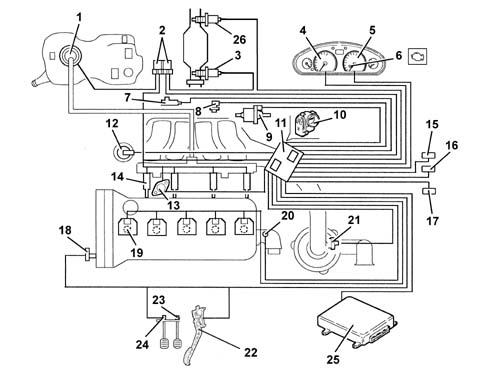
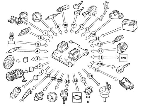
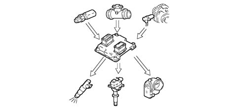
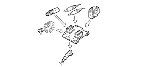
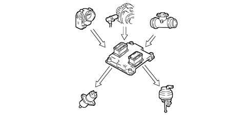
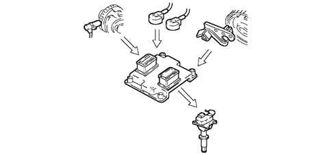
VIEW OF ASSEMBLY1 - Fuel pump2 - Relays3 - Lambda sensor (upstream)4 - Speedometer5 - Rev counter6 - Injection warning light7 - Knock sensors8 - RPM sensor9 - Fuel vapour recirculation solenoid10 - Throttle body built into DVE11 - Engine Control Node12 - Modular intake manifold solenoid13 - Phase transformer14 - Injectors15 - Climate control system connector16 - Tester connector17 - CODE connector18 - Timing sensor19 - Ignition coil20 - Coolant temperature sensor21 - Air flow meter with air temperature sensor22 - Accelerator pedal potetiometer23 - Brake pedal switch24 - Clutch pedal switch25 - Automatic transmission control unit (where necessary)26 - Lambda sensor (downstream)Diagram showing information entering/leaving the ENGINE MANAGEMENT NODE1 - Fuel pump2 - Air conditioning compressor3 - Fan4 - Lambda sensors downstream of the catalytic converter5 - Quadrinary6 - Brake pedal switch7 - Timing sensor8 - Speedometer9 - Lambda sensor upstream of the pre-catalyzer10 - Coolant temperature sensor11 - Knock sensor (two)12 - RPM sensor13 - Accelerator pedal potetiometer14 - Air flow meter with air temperature sensor15 - Battery16 - Clutch pedal switch17 - Throttle body built into DVE18 - CAN line (for communication with ABS/ASR control units)19 - Lancia CODE20 - Diagnotic socket21 - Fuel vapour recirculation solenoid22 - Ignition coil23 - Injection warning light24 - Modular intake manifold solenoid25 - Rev counter26 - Phase transformer27 - InjectorsOPERATION
Operating strategies
Introduction
Injection systemThe essential conditions to be met by the air-fuel mixture for efficient operation of engines with controlled ignition systems are mainly as follows:
- the metering (air/fuel ratio) must be kept as close as possible to stoichiometric levels to assure maximum catalytic converter conversion capacity (max. efficiency).
- homogeneity of the mixture, consisting of petrol distributed throughout the air as finely and uniformly as possible.
Information that the Engine Control Node processes to control optimum metering is received by electrical signals emitted by:
- air flow meter and air temperature sensor, for the exact quantity of air taken in
- rpm sensor that generates an alternating single-phase signal whose frequency is an indicator of engine rpm. The Engine Management Node uses this signal to detect MISFIRE
- throttle potentiometer, to detect the required acceleration conditions
- coolant temperature sensor on the thermostat
- Lambda sensors to determine the oxygen content of the exhaust gases and, via the downstream sensor, to diagnose the efficiency of the catalyzers.
Ignition systemThe ignition system is static, inductive discharge type (i.e. without a HT distributor) with power modules located inside the Engine Control Node.The ignition system is arranged so that each coil supplies the spark plugs of the associated cylinder.The advantages of this solution are:
- lower electrical overload;
- guaranteed constant discharge on each spark plug.
The Engine Control Node contains a memory map with a set of optimum ignition advance values (for the cylinder in combustion phase) that the engine can adopt according to the required speed and engine load.The Engine Control Node corrects the advance value mainly on the basis of:
- engine coolant temperature
- intake air temperature
- detonation
- throttle valve position.
Information that the Engine Control Node processes to control the coils is received by electrical signals emitted by:
- air flow meter and air temperature sensor, for the exact quantity of air taken in
- rpm sensor that generates an alternating single-phase signal whose frequency is an indicator of engine rpm
- 2 detonation sensors (at the rear of the cylinder block/crankcase, one between the 1st and 2nd cylinders, the other between the 4th and 5th) to recognize which cylinder detonation is taking place in and therefore correct the ignition advance.
- throtle position potentiometer to recognise minimum, partial and full-gas load conditions.
- timing sensor.
Self-learning
The Engine Control Node runs its initialisation program under the following conditions:Engine Management Node removing/refitting or replacementremoving-refitting or replacing the throttle casing.The values stored by the Engine Control Node are maintained when the battery is disconnected.System self-adjustment
The Engine Control Node is equipped with a self-adjustment function that is designed to recognize the changes that take place in the engine due to the processes of bedding in and ageing of both the components and the engine itself in time.These changes are memorized in the form of modifications to the basic map and are designed to adapt the operation of the system to the gradual alterations in the engine and the components compared with when they were new.This self-adjustment function also makes it possible to compensate for the inevitable differences in any replacement components (due to production tolerances).The Engine Control Node modifies the basic map in relation to engine specifications when new on the basis of an exhaust gas analysis.The self-adjustment parameters are not deleted if the battery is disconnected.Self-diagnosis
The control unit self-diagnostic system checks that the system is working properly and indicates any irregularities by means of an MIL warning light in the instrument panel with a standardized ideogram and colour laid down by European regulations. This warning light indicates engine management faults and also faults detected by EOBD diagnostic strategies.The MIL warning light operating (mil) strategy is as follows:
- with the ignition on, the warning light comes on and remains on until the engine has been started up. The control unit self-diagnostic system checks the signals coming from the sensors comparing them with the permitted limits.
Fault indication during start up:
- failure of the warning light to go out when the engine has been started indicates that there is an error memorized in the control unit.
Fault indication during operation:
- the warning light comes on in flashing mode to indicate possible catalytic converter damage due to misfiring.
- the warning light comes on in constant mode to indicate the presence of engine management or EOBD diagnostic errors.
RECOVERYFrom time to time the Engine Control Node defines the type of recovery according to the components that are faulty. The recovery parameters are managed by components that are not faulty.Code recognition
When the Body Computer receives an ignition ON signal, it communicates wtih the Engine Control Node to allow start-up. For vehicles with Passive Entry, see [DF55].Cold starting check
The following occurs in cold starting conditions:
- a natural weakening of the mixture which causes poor evaporation (poor turbulence of the particles of fuel at low temperatures)
- reduced evaporation of the fuel
- condensation of the fuel on the inner walls of the intake manifold
- higher lubrication oil viscosity.
The Engine Management Node recognizes this condition and corrects the basic injection time:
- coolant temperature
- intake air temperature
- battery voltage
- engine rpm.
The ignition advance only depends on the number of revs and the temperature of the engine coolant.Whilst the engine is warming up, the Engine Management Node operates the motorized throttle to regulate the quantity of air required to ensure that the engine does not cut out.The rotation speed decreases proportionally as the engine temperature increases until the nominal value is reached when the engine has warmed up.Combustion - lambda sensor check
In EOBD systems, the Lambda sensors are all the same type and located upstream of the catalytic conversion system and downstream of the converter. The upstream sensor determines the control of the mixture strength known as the 1st closed loop for the upstream sensor. The sensor downstream of the catalyzer is used for the fault diagnosis of the catalyzer and for modulating the 1st loop control parameters. The second loop is therefore adaptive to make up for production discrepancies and slight drift that upstream sensor responses could experience due to ageing and contamination. This control is known as 2nd loop control (downstream sensor closed loop).Check on phase transformer and modular intake manifold
In order to ensure the optimum quantity of air introduced by the engine, the Engine Management Node controls:
- the intake timing in two angular positions
- the geometry of the intake manifolds in two lengths.
The Engine Management Node sets the "open" stage at the maximum torque speed:
- cam advance of 18° engine
- intake chamber long ducts.
The Engine Management Node sets the "closed" stage at the maximum power speed and the minimum speed:
- cam in normal position
- intake chamber short ducts.
In the other engine operating conditions, the Engine Management Node selects the most suitable configuration for optimum performance, consumption and emissions.In the release stage the chamber intake ducts are always short.Knock control
The Engine Management Node detects the presence of detonation (engine knock) by processing the signal coming from the relevant sensors.The Engine Management Node continuously compares the signals coming from the sensors with a threshold which is, in turn, continually updated to take into account background noise and engine ageing.The Engine Management Node is therefore capable of detecting the presence of detonation (or the onset of detonation) in each individual cylinder and reduces the ignition advance in the cylinder involved (in steps of 3° up to a maximum of 6°) until the phenomenon disappears. Later on, the advance is gradually restored to the basic value (in steps of 0.8°).In acceleration conditions, a higher threshold is used to take into account the increased noise of the engine in these circumstances.The detonation control logic also has a self-adjustment function which memorizes the reductions in the advance that are continuously repeated in order to adapt the map to the different conditions that the engine finds itself in.Check on enrichment during acceleration
| ... DATA ERROR - CROPPED TEXT | Ошибка данных - Текст обрезан ... |
|---|