3360113 - 1080B EXHAUST EMISSION CONTROL SYSTEM
OPERATION
Lambda sensors
These are planar type and located upstream and downstream of the catalytic converter.The upstream sensor determines mixture control, known as the first loop.The control unit controls and manages injection so that the air/fuel ratio is always sufficiently close to a stoichiometric level to maximise catalytic converter efficiency. The mixture is enriched to ensure maximum performance under conditions of full power and high use.The downstream sensor diagnoses the conversion efficiency of the converter/s.Then:
- Lambda = 1 ideal mixture
- Lambda > 1 lean mixture
- Lambda < 1 rich mixture
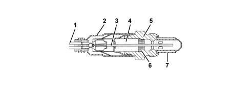
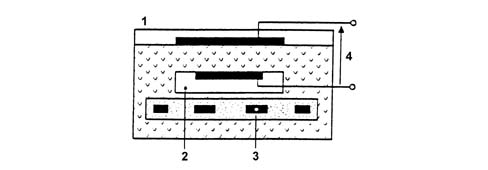
a - Rich mixture (lack of air)b - Lean mixture (excess air)The Lambda sensors are in contact with exhaust gases and generate an electrical signal with voltage dependent on oxygen level in the gas. This voltages alters abruptly when mixture composition deviates from Lambda = 1.The injection control unit manages Lambda sensor heating in proportion with exhaust gas temperature.This avoids thermal shocks to the ceramic case due to contact with condensed water present in exhaust gas when the engine is cold.The measurement chamber and heater are built into a planar (laminated) ceramic element that offers the benefit of fast chamber heating. This allows closed loop (lambda = 1) control within 10 second of engine start-up.1 - Connection cable2 - Protective sleeve3 - Planar sensor element4 - Ceramic mounting pipe5 - Sensor housing6 - Ceramic seal7 - Protective pipeThe Lambda sensor works on the principle of an oxygen concentration chamber with solid electrolyte.The measurement chamber surfaces are coated with microporous layers of noble material.1 - Exhaust gas2 - Reference air passage3 - Heater4 - Lambda sensor voltageSpecifications:
- Fuel system: 12V
- Internal resistance: 0.5 - 1 kOhm
Catalytic converter
The three-way catalytic converter makes it possible to keep down the levels of the three pollutant gases in the exhaust gases at the same time:
- unburnt hydrocarbons (HC);
- carbon monoxide (CO);
- nitrogen oxides (NOx).
Two types of chemical reaction take place inside the converter:
- oxidation of CO and HC to carbon dioxide (CO2) and water (H2O)
- reduction of Nox to nitrogen (N2).
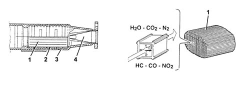
The converter consists of a structure, a metal gauze suppoart to dampen impacts and vibrations and a stainless steel outer casing that is resistant to high temperatures and atmospheric agents. The honeycomb structure is made from a ceramic material covered in an extermely thin layer of catalytically active substances, platinum or rhodium, which accelerated the chemical decomposition of the harmful substances contained in the exhaust gases which, when passing through the core cells at temperatures above 300° - 350°C, activate the catalyzers setting off the oxidation/reduction reactions. | The nobile metals in the catalytic converter suffer chemical attack if lead is present, partly due to the high temperature inside the converter. For this reason, the use of leaded fuel should be be avoided, otherwise the converter will be rapidly and irreversibly put out of service. Never use leaded fuel, even for a short time in an emergency. |
1 - One-piece ceramic structure2 - Metal mount3 - Outer casing4 - Perforated steel cone