3363717 - Introduction - FITTINGS
DOOR
SPECIFICATIONS
The layout of the panel functional
elements has been designed to allow the correct interaction with
the body of the occupant in the case of a side impact.They are soft and smooth in the top section,
whilst the protrusion of the armrest is made harmless by the fact
that it collapses and presents no risk of injury to the abdomen.
The door also features a Carrier which, in addition to supporting
the electric window motor, guides and various cables, is integrated
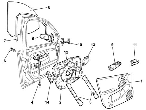
with the actual door and performs a structural function.1 - Door inner panel
2 - Carrier
3 - Electric window guides
4 - Opening mechanism bowden cable
5 - Rear view mirror
6 - Door lock catch
7 - Seal
8 - Window
9 - Door control panel
10 - Door check strap
11 - Door interior opening handle
12 - Electric window motor
13 - Door node
14 - LockSUNROOF
INTRODUCTION
All vehicles can be fitted as
an option with a laminated glass sun roof which can be operated
by a remote control on certain versions.The laminated glass sun roof and electronically
adjusted PVC blind make it possible to provide excellent light for
the passenger compartment when the roof is closed and an intake
of air when it is open through the six possible adjustment positions.The system is also fitted with an anti-crush
safety device which stops the movement of the roof if there are
any obstacles present.SPECIFICATIONS:
The sun roof assembly consists
of a system of mechanism which adjust the position of the five glass
plates reinforced by an aluminium frame. The sun roof is opened
by an electric motor and adjusted through a 6 position selector
( including zero '0'); in particular, the first roof plate has a
rocker movement whilst the other 4 plates have a traversing movement.The sun roof system is also fitted with
a sliding sun blind (electronically operated by a second electric
motor) whose opening cannot be lower than the opening of the actual
plates.The selection controls are located in the
centre courtesy light and are managed by two control unit (master
for the front and slave for the rear) which interact with each other
controlling the action of the two built-in motors at the longitudinal
edges of the roof.The movement mechanisms are fitted in the
aluminium guides and driven by a clock spring operated by the front
electric motor.There are also drainage channels on the
four front and rear sides of the frame which drain off water that
could filter from the seals through pipes with anti-reflux valves
(which will probably be eliminated).Safety is guaranteed by an anti-crush system
which is activated for the entire range of movement when both the
sun blind and the roof are being closed.COMPOSITION
The sun roof consists of:
- a frame comprising two aluminium guides in which the
movement mechanisms slide and two crossmembers, front and rear,
made from plastic which define the width of the roof and complete
the frame
- a right and left mechanism system, fitted in the aluminium
guides, for moving the glass plates
- a sliding PVC roller sun blind with metal reinforcement
ribs and a an aluminium profile front crossmember which slides along
the entire length of the roof and is operated by a second electric
mitor;
- five reinforced glass plates, each with a frame;
- two electric movement motors which interact with one
another through the respective built-in control units (motor current
absorption: when moving plates and blind about 10A per motor)
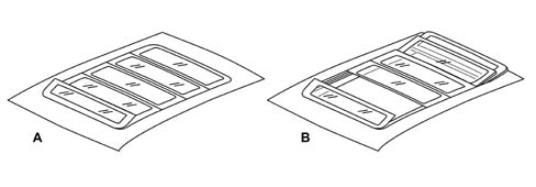
The diagram below shows the laminated sun
roof opening system.1 Control panel
2 First plate selector in tilt positionOPERATION
The operating logic described
below is achieved through the action of two electric motors managed
by two electronic control units (known as Master and Slave) which
control the laminated glass roof and the sun blind, respectively. The sun roof moves along the sliding guides,
positioned on the frame, through a bowden cable (rack) operated
by an electric motor located in the front part of the roof frame.
The action of the motor causes the vertical movement of the lift
lever for the first plate which produces the two permitted positions
for the spoiler, later on the cable acts on the attachment brackets for
the other plates moving them until the total permitted opening is
completed. The sun roof is fitted with a sun blind
underneath which can be operated indepdently (with the plates closed)
using the two buttons on the courtesy light and/or automatically
through the (Master) control unit which, when the sun roof is opening, co-ordinates
the alignment of the blind with the opening position of the second
plate. The closing of the blind is subject to the opening position
of the plates: the blind cannot, in effect, be closed with the glass
open.The sun roof may be moved manually
by means of the selector under the following conditions:
- with the ignition key in the Key On position
- the roof can be moved remotely, i.e. when the control
unit receives the control signals from the Body Computer.
 | The Master Control Unit is connected
in series to the Body Computer therefore a problem with the latter
will affect the roof operating logic. |
| The anti-crush safety function
is always active during movement, slide/tilt operations (including
operations controlled remotely). |
| Do not disconnect the battery
or supply the sun roof with power during motion. If this happens,
the control units lose their memory and must be reset
as described in the Chapter 'Resetting Control Unit Memory' up
to step 3. |
Anti-crush function
In order to limit possible damage
to passengers or objects whilst the roof is moving, an anti-crush
safety function is included. The safety system is present for the
entire blind closing range on the front profile of the second plate
during sliding and on the rear edge of the first plate during tilting.After detecting a force which is greater
than a pre-set level, the Master Control Unit (fitted at the front)
which governs the roof plates, immediately stops the movement in
the case of the first plate and completely reverses the tilting
movement, whilst in the case of the second plate it orders the immediate
halting and reversal of the movement for a travel of 200 mm.The function is also activated during closure
on the front profile of the blind and is operated by the Slave Electronic
Control Unit (fitted at the rear) after an obstacle (e.g. finger,
hand) is encountered, guaranteeing the reversal of the movement
for a travel of 200 mm.The anti-crush safety function can be excluded
by placing the selector in the inhibitor position which works within
5 secs. After the roof has stopped, when the rotary selector is
pressed in position '0' the control remains activated until the
roof is closed or until the selector is released: in this case the
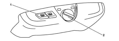
function is not activated.Selector and control panel
The controls, located in the
centre courtesy light, include the six position rotary selector
(including '0') (clockwise direction for opening, five positions
and anti-clockwise direction for closing) and the two one-touch
type blind opening/closing buttonsA - Opening of first plate in tilt position
B - Sliding of other platesCONTROL PANEL:
- The two buttons open and close the blind
- if either button is pressed again the blind stops in
the desired position
SELECTOR POSITIONS:
- 0 roof completely closed
- 1 minimum tilt position for first plate
- 2 - maximum tilt position for first palte and second
plate retracted
- 3 - 5 sliding positions for second plate and other plates
retracted
 | The opening/closing of the sun
blind is subject to the position of the glass plates. Whilst the
plates are opening the blind moves automatically reaching a position
where it covers the glass when it is completely open, whilst during closure
the blind is about 30 mm ahead of the second plate and stops 30
mm from the end of travel position. |
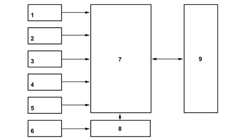
Control units
The table below summarizes the
functions of the two control units1 - ANTI-CRUSH FUNCTION
2 - OPENING/CLOSING ROOF USING SELECTOR
3 - SPEEDOMETER SIGNAL
4 - LIGHTING SIGNAL
5 - MANUAL BLIND CONTROL
6 - ROOF CLOSING REMOTE CONTROL
7 - MASTER ELECTRONIC CONTROL UNIT (ROOF)
8 - BODY COMPUTER NODE
9 - SLAVE ELECTRONIC CONTROL UNIT (BLIND)The movement of the sun roof
and the blind is governed by the Master Control Unit which manages
a second Slave Control Unit both of which are housed in casings
on the motor. These electric devices process the signals coming
from either the selector/control panel or the remote control, through
the Body Computer and also control the anti-crush safet function.The function is controlled by the control
unit, which receives position and speed information from Hall effect
sensors fitted to the motor. When effort in excess of a certain
threshold is detected, corresponding to a higher current uptake,
this is interpreted as an obstacle. The control unit then stops
the roof immediately and moves it back in the opposite direction.The control unit also receives a vehicle
speed signal because the vacuum created at certain speeds could
change the effort required to close the roof and under certain conditions
this could be interpreted as an impediment. The control unit therefore uses
this signal to ensure movement is not halted inadvertantly.Resetting the control unit memory
The initialization procedure
must be carried out each time the sun roof control units are changed,
whilst if there is a drop in the supply whilst he roof is working
(failed supply from the battery) the procedure should be carried
out up to step 3. The initialization procedure is illustrated
below:
- 1 turn the rotary selector knob to position '0' (fully
closed)
- 2 keep the rotary selector pressed (for longer than
2 secs): the roof closes
- 3 wait, keeping the roof completely closed until the
blind has clicked shut twice (Hard closing position and then returns to
the Soft closing position)
- 4 release the selector and press it again within 3 secs.
- 5 keep the selector pressed until the roof (glass and
blind) is completely open and then closed again
- 6 release the selector;
The initialization is completed at this
point. | in the case of repairs to or problems
with the Body Computer or a break in the battery connections, the
motor absorption may be 26+26 A max |
The initialization process cannot
not take place successfully if one of the following conditions occurs:
- The rotary selector has not been placed in position
'0';
- The selector has ben released during the manoeuvre;
- The blind operating button has been pressed;
If the process has not been successfully
concluded it should be repeated.Control unit pin out
Master Control Unit| PIN NO. | FUNCTION |
|---|
| 4 | BATTERY + |
| relay | POWER GND |
| relay | ELECTRONIC GND |
| 6 | SERIAL COMMUNICATION |
| 5 | GL/CLOSED AUTHORIZATION |
| 3 | SPEED SIGNAL |
| 7 | FREE (contact strip 1) |
| 8 | FREE (contact strip 2) |
| 10 | POTI 1 |
| 9 | POTI 2 |
| 12. | POTI 3 |
| 11. | POTI 4 |
Slave Control Unit| PIN NO. | FUNCTION |
|---|
| relay | SERIAL COMMUNICATION |
| 3 | SERIAL COMMUNICATION |
| 5 | BATTERY + |
| 7 | BATTERY + |
| 9 | EARTH |
| 11. | EARTH |
Adjustments
Complete sun roof
During repair operations (replacing
the frame or complete roof) or in the case of water or air penetration
it may prove necessary to adjust the roof even if this adjustment
requires great care and attention.The procedure is carried out (with the roof
secured to the bodyshel by tightening the coaxial screws to the
adjusters - 7 Nm) using the 4 adjustment nuts (the roof is raised
when they are undone using a 19 mm spanner and lowered micrometrically when
they are tightened) located at the ends of the aluminium guides
on the actual fram| ... DATA ERROR - CROPPED TEXT | Ошибка данных - Текст обрезан ... |
|---|