3363555 - 1016E10 SINGLE CYLINDER HEAD, REMOVED - OVERHAUL
| Description | Code | |
|---|---|---|
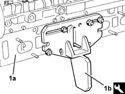
| 1b | Support | 1.860.470.000 |
| Description | Connector | |
|---|---|---|
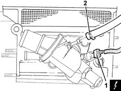
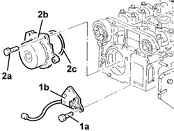
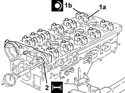
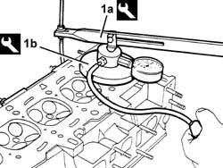
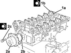
| 1 | Engine temperature sending unit | K36 |
| Description | Connector | |
|---|---|---|
| 2 | Timing sensor | K47 |
| Description | Code | |
|---|---|---|
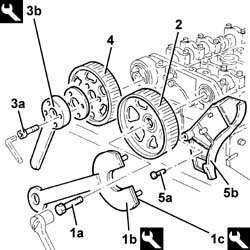
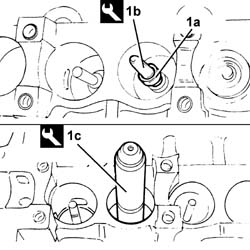
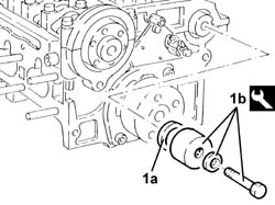
| 1b | Support for counter-torque | 1.860.831.000 |
| Description | Code | |
|---|---|---|
| 1c | Counter-torque | 1.860.848.000 |
| Description | Code | |
|---|---|---|
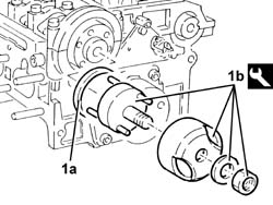
| 3b | Counter-torque | 1.860.856.000 |
| Measurement | Value | ||
|---|---|---|---|
| - | End float (mm) | 0.10 - 0.23 |
| Description | Code | |
|---|---|---|
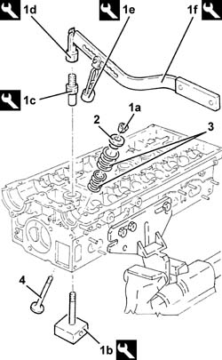
| 1b | Valve retaining base | 1.860.786.000 |
| Description | Code | |
|---|---|---|
| 1c | Extension | 1.860.787.000 |
| Description | Code | |
|---|---|---|
| 1d | Lever hook | 1.860.788.000 |
| Description | Code | |
|---|---|---|
| 1e | Chamber | 1.860.840.000 |
| Description | Code | |
|---|---|---|
| 1f | Lever | 1.860.790.000 |
| Description | Code | |
|---|---|---|
| 1b | Extractor | 1.860.989.000 |
| Description | Code | |
|---|---|---|
| 1b | Drift | 1.860.395.000 |
| Measurement | Value | ||
|---|---|---|---|
| - | Lower plane planarity (mm) | 0.1 |
| Measurement | Value | ||
|---|---|---|---|
| - | Minimum permitted height after regrinding (mm) | 140,85 |
| Measurement | Value | ||
|---|---|---|---|
| - | Combustion chamber volume (cc) | 51,486 |
| Measurement | Value | ||
|---|---|---|---|
| - | Inlet valve stem diameter (mm) | 6.975 - 6.990 |
| Measurement | Value | ||
|---|---|---|---|
| - | Exhaust valve stem diameter (mm) | 6.960 - 6.975 |
| The valve guide diameter should be checked with the guide fitted on the head. |
| Measurement | Value | ||
|---|---|---|---|
| - | Valve guide diameter (mm) | Inlet | 7,022 - 7,040 |
| Exhaust | 7,022 - 7,040 | ||
| Measurement | Value | ||
|---|---|---|---|
| - | Outer diameter (mm) | 32.959 - 32.975 |
| Measurement | Value | ||
|---|---|---|---|
| - | Hydraulic tappet housing diameter (mm) | 33.000 - 33.025 |
| Measurement | Value | ||
|---|---|---|---|
| - | Inner spring length released (mm) | 31,20 |
| Measurement | Value | ||
|---|---|---|---|
| - | Inner spring length (mm) | 29.5 | |
| Test load (daN) | 8.650 - 7.550 | ||
| Measurement | Value | ||
|---|---|---|---|
| - | Inner spring length (mm) | 23.4 | |
| Test load (daN) | 18.060 - 16.260 | ||
| Measurement | Value | ||
|---|---|---|---|
| - | Outer spring length released (mm) | 46,00 |
| Measurement | Value | ||
|---|---|---|---|
| - | Outer spring length (mm) | 36.80 | |
| Test load (daN) | 22.780 - 20.580 | ||
| Measurement | Value | ||
|---|---|---|---|
| - | Outer spring length (mm) | 27.6 | |
| Test load (daN) | 44.965 - 41.365 | ||
| Measurement | Value | ||
|---|---|---|---|
| - | Diameter of v.d.f. inlet bearing (mm) | 49,985 - 50,000 |
| Measurement | Value | ||
|---|---|---|---|
| - | Journal diameter (mm) | 26.000 - 26.015 |
| Measurement | Value | ||
|---|---|---|---|
| - | Thickness of v.d.f. inlet camshaft half-bearing (mm) | 2,998 - 2,982 |
| Measurement | Value | ||
|---|---|---|---|
| - | Operating clearance (mm) | 0,034 - 0,086 |
| Measurement | Value | ||
|---|---|---|---|
| - | Nominal inlet shaft cam lift (mm) | 9.0 |
| Measurement | Value | ||
|---|---|---|---|
| - | Nominal exhaust camshaft cam lift (mm) | 9.0 |
| Fastening | Component | Ø | Value(daNm) | |
|---|---|---|---|---|
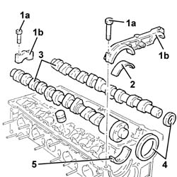
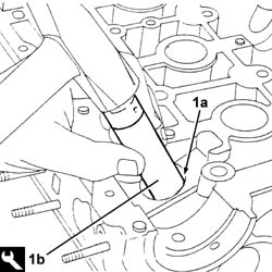
| 1b | Bolt | CAMSHAFT CAPS | M7 | (Cylinder head side) 1.4 - 2.0 |
| Measurement | Value | ||
|---|---|---|---|
| - | Inlet camshaft support diameter v.d.f. (mm) | 56,015 - 55,990 |
| Measurement | Value | ||
|---|---|---|---|
| 2 | Camshaft support diameter (mm) | 26.045 ÷ 26.070 |
| Measurement | Value | ||
|---|---|---|---|
| - | Outer diameter (mm) | 13.010 - 13.030 |
| Description | Code | |
|---|---|---|
| 1b | Fitting tool | 1.860.812.000 |
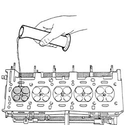
| Before fitting the new valve guides, heat the cylinder head in the oven to a temperature of 80 - 100 °C. |
| Measurement | Value | ||
|---|---|---|---|
| - | Inner diameter (reaming) (mm) | 7.022 - 7.040 |
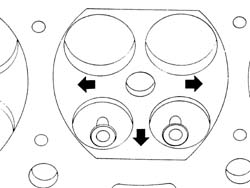
| Grind the valve seats each time the valves or the valve guides are replaced. |
| Measurement | Value | ||
|---|---|---|---|
| - | Width of band in contact with valve (mm) | ~ 2 |
| Description | Code | |
|---|---|---|
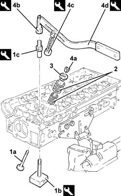
| 1a | Lever | 1.860.490.000 |
| Description | Code | |
|---|---|---|
| 1b | Test equipment | 1.895.868.000 |
| Description | Code | |
|---|---|---|
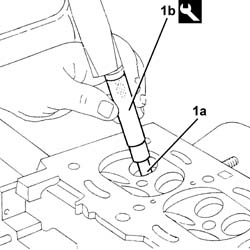
| 1b | Drift | 1.860.813.000 |
| Description | Code | |
|---|---|---|
| 1c | Fitting tool | 1.860.454.000 |
| Description | Code | |
|---|---|---|
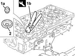
| 1b | Valve retaining base | 1.860.786.000 |
| Description | Code | |
|---|---|---|
| 1c | Extension | 1.860.787.000 |
| Description | Code | |
|---|---|---|
| 4b | Lever hook | 1.860.788.000 |
| Description | Code | |
|---|---|---|
| 4c | Chamber | 1.860.840.000 |
| Description | Code | |
|---|---|---|
| 4d | Lever | 1.860.790.000 |
| Fastening | Component | Ø | Value(daNm) | |
|---|---|---|---|---|
| 1b | Bolt | CAMSHAFT CAPS | M7 | (Cylinder head side) 1.4 - 2.0 |
| Fastening | Component | Ø | Value(daNm) | |
|---|---|---|---|---|
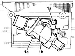
| 2c | Bolt | COOLANT PUMP | M8 | (Cylinder head side) 2.3 - 3.3 |
| Fastening | Component | Ø | Value(daNm) | |
|---|---|---|---|---|
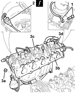
| - | Bolt | CAM ANGLE SENSOR | - | 0,9 - 1,2 |
| Description | Code | |
|---|---|---|
| 1b | Fitting tool | 1.860.824.000 |
| Description | Code | |
|---|---|---|
| 1b | Fitting tool | 1.860.844.000 |
| Fastening | Component | Ø | Value(daNm) | |
|---|---|---|---|---|
| - | Bolt | PROTECTION COVER GUARDS/SUPPORTS | - | 0,9 - 1,2 |
| Fastening | Component | Ø | Value(daNm) | |
|---|---|---|---|---|
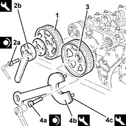
| 2a | Bolt | TIMING DRIVEN PULLIES | M6 | (Inlet camshaft side) 0.9 -1.2 |
| Description | Code | |
|---|---|---|
| 2b | Counter-torque | 1.860.856.000 |
| Fastening | Component | Ø | Value(daNm) | |
|---|---|---|---|---|
| 4a | Bolt | TIMING DRIVEN PULLIES | M12 | (Exhaust camshaft side) 11.00 - 15.9 |
| Description | Code | |
|---|---|---|
| 4b | Support for counter-torque | 1.860.831.000 |
| Description | Code | |
|---|---|---|
| 4c | Counter-torque | 1.860.848.000 |
| Fastening | Component | Ø | Value(daNm) | |
|---|---|---|---|---|
| - | Bolt | THERMOSTAT | M8 | (Cylinder head side) 2.3 - 3.3 |
| Fastening | Component | Ø | Value(daNm) | |
|---|---|---|---|---|
| - | Nut | INLET MANIFOLD | M8 | (Cylinder head side) 2.3 - 3.3 |
| Fastening | Component | Ø | Value(daNm) | |
|---|---|---|---|---|
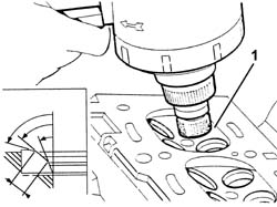
| - | - | SPARK PLUGS | M14 | (Cylinder head side) 2.5 - 3.0 |
| Description | Code | |
|---|---|---|
| - | Support | 1.860.470.000 |