3363670 - 5550AA Checking stalk unit operation
Check the continuity between the contacts for the connectors on the steering column switch unit in the different positions: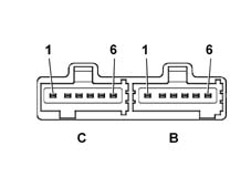
Side lights control check
- with the control on symbol 0, check the state of the contact at connector B between pins 5 and 6: open circuit
- with the control on 'side lights', check the state of the contact at connector B between pins 5 and 6: open circuit
Dipped headlamps control check
- with the control on 'side lights', check the state of the contact between pin 3 (connector B) and pin 5 (connector C): open circuit
- with the control on 'dipped headlamps' check the state of the contact between pin 3 (connector B) and pin 5 (connector C): closed circuit
Main beam headlamps control check
- with the control in the rest position, check the state of the contact between pin 2 (connector B) and pin 5 (connector C): open circuit
- with the control on 'main beam headlamps', check the state of the contact between pin 2 (connector B) and pin 5 (connector C): closed circuit
Flasher control check
- with the flasher lever released, check the state of the contact between pin 2 (connector B) and pin 5 (connector C): open circuit
- with the flasher lever operated, check the state of the contact between pin 2 (connector B) and pin 5 (connector C): closed circuit
'AUTO' lights control check
- with the control in position '0', check the state of the contact between pin 4 (connector B) and pin 5 (connector C): open circuit
- with the control in the 'AUTO' position, check the state of the contact between pin 4 (connector B) and pin 5 (connector C): closed circuit
Direction indicators control check
- with the control lever in the 'centre' position, check the state of the contact between pins 5 (connector C) and 6 (connector C): open circuit and between pins 1 (connector B) and 5 (connector C): open circuit
- with the control lever in the 'left' downwards position check the state of the contact between pins 5 (connector C) and 6 (connector C): closed circuit with the control lever in the 'right' upwards position check the state of the contact betweeen pins 1 (connector B) and 5 (connector C): closed circuit.