3362606 - 1004B24 power unit with manual gearbox with hydraulic selection - r r

 | Name | Connector |
|---|---|---|
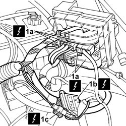
| 1a | Engine compartment junction unit | B1A |
| Name | Connector |
|---|---|---|
| 1a | Engine compartment junction unit | B1B |
| Name | Connector |
|---|---|---|
| 1a | Engine compartment junction unit | B1C |
| Name | Connector |
|---|---|---|
| 1a | Engine compartment junction unit | B1D |
| Name | Connector |
|---|---|---|
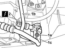
| 1b | Front/engine connection | D4 |
| Name | Connector |
|---|---|---|
| 1c | Data not available yet | D9 |
| Name | Connector |
|---|---|---|
| 1a | "Selespeed gearbox electric pump" | N47 |
| Name | Connector |
|---|---|---|
| 1b | "Selespeed gearbox sensors coupling" | D79 |
| Name | Connector |
|---|---|---|
| - | Sensor on clutch | K99 |


 | Name | Country |
|---|---|---|
| - | Rapid connector | 1.870.684.000 |
| Name | Connector |
|---|---|---|
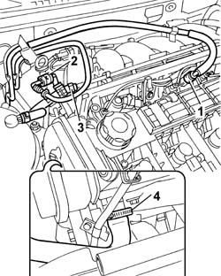
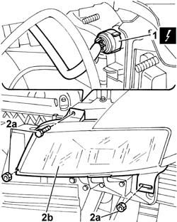
| 1 | Air flow meter | K41 |
| Name | Connector |
|---|---|---|
| 1 | Horn | P5 |

| Name | Connector |
|---|---|---|
| 2 | Linear sensor for fans | K120 |

| Name | Connector |
|---|---|---|
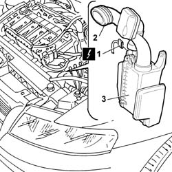
| 1 | Right headlamp | F11 |
| Name | Connector |
|---|---|---|
| 1 | Left headlamp | F10 |
| Name | Connector |
|---|---|---|
| 1 | Air-Bag front sensor | K39 |


| Name | Connector |
|---|---|---|
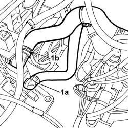
| 2a | Lambda sensor on pre-catalyzer | K15 |
| Name | Connector |
|---|---|---|
| 2b | Lambda sensor on pre-catalyzer -2 | K16 |


| Take great care when rotating and removing the engine not to damage the components fitted on the vehicle. |
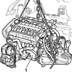
| Take great care when fitting the engine not to damage the components fitted on the vehicle. |
 | Fastening | Component | Ø | Value(daNm) |
|---|---|---|---|---|
| - | Nut | GEARBOX SIDE RUBBER MOUNT | M12 | 9 |
| Fastening | Component | Ø | Value(daNm) |
|---|---|---|---|---|
| - | Bolt | ENGINE MOUNT TIMING SIDE | M10 x 1.25 | (Bodyshell side) 5 |
| Fastening | Component | Ø | Value(daNm) |
|---|---|---|---|---|
| - | Nut | ENGINE MOUNT TIMING SIDE | M12 x 1.25 | (Engine side) 7.5 |
| Fastening | Component | Ø | Value(daNm) |
|---|---|---|---|---|
| - | Bolt | A.C/ CONDENSER COMPRESSOR( PIPE..) | M10 x 1.25 | 3.5 |
| Fastening | Component | Ø | Value(daNm) |
|---|---|---|---|---|
| - | Bolt | REACTION ROD | M12 x 1.25 | 13.5 |
| Fastening | Component | Ø | Value(daNm) |
|---|---|---|---|---|
| - | Bolt | REACTION ROD | M12 x 1.25 | 7.5 |
| Fastening | Component | Ø | Value(daNm) |
|---|---|---|---|---|
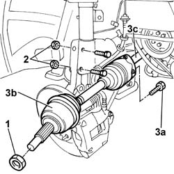
| - | Bolt | FRONT DAMPER | M10 x 1.25 | (Steering knuckle) 7 |
| Fastening | Component | Ø | Value(daNm) |
|---|---|---|---|---|
| - | Bolt | FRONT DAMPER | M10 x 1.25 | (Steering knuckle) 7 |
| Fastening | Component | Ø | Value(daNm) |
|---|---|---|---|---|
| - | Nut | FRONT HUB WITH BEARINGS | M24 | 7 + 62° |
| Fastening | Component | Ø | Value(daNm) |
|---|---|---|---|---|
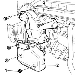
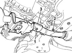
| - | Nut | CATALYTIC CONVERTER (ONE) | M8 | (To the flexible centre section) 2.5 |
| Fastening | Component | Ø | Value(daNm) |
|---|---|---|---|---|
| - | Nut | PRE-CAT CONVERTOR/CAT CONVERTOR PIPE | M10 x 1.25 | (Oil sump) 5 |
| Fastening | Component | Ø | Value(daNm) |
|---|---|---|---|---|
| - | Nut | CATALYTIC PRE-CONVERTER | M8 | 2.5 |
| Name | Connector |
|---|---|---|
| - | Lambda sensor on pre-catalyzer | K15 |
| Name | Connector |
|---|---|---|
| - | Lambda sensor on pre-catalyzer -2 | K16 |
| The bolts fixing the front end to the struts are tightened to a torque of 3 daNm. |
| Name | Connector |
|---|---|---|
| - | Air-Bag front sensor | K39 |
| Name | Connector |
|---|---|---|
| - | Right headlamp | F11 |
| Name | Connector |
|---|---|---|
| - | Left headlamp | F10 |
| Fastening | Component | Ø | Value(daNm) |
|---|---|---|---|---|
| - | Bolt | BONNET LID LOCK/S | M6 | 0.8 |
| Name | Connector |
|---|---|---|
| - | Linear sensor for fans | K120 |
| Name | Connector |
|---|---|---|
| - | Horn | P5 |
| Name | Connector |
|---|---|---|
| - | Air flow meter | K41 |
| Name | Connector |
|---|---|---|
| - | Sensor on clutch | K99 |
| Name | Connector |
|---|---|---|
| - | "Selespeed gearbox electric pump" | N47 |
|
|---|
| ... DATA ERROR - CROPPED TEXT | Ошибка данных - Текст обрезан ... |
|---|