3363586 - 2110B20 MANUAL GEARBOX (5-6SPEED) WITH DIFFERENTIAL - DISMANTLING AND REASSEMBLY - WASH AND CHECK PARTS - REPLACE SYNCHRONISERS AND INTERNAL CONTROLS IF NECESSARY
| The main shaft cannot be dismantled on the Selespeed version. |
| Description | Code | |
|---|---|---|
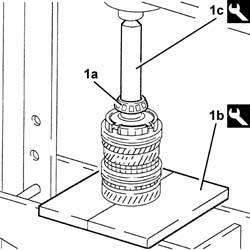
| 1c | Support | 1.870.644.001 |

| Two mechanics are needed for this operation. |
| Description | Code | |
|---|---|---|
| 1b | Support | 1.871.001.014 |

| Description | Code | |
|---|---|---|
| 1b | Flange | 1.847.017.004 |
| Description | Code | |
|---|---|---|
| 1c | Mallet | 1.840.206.001 |


| The gearbox casing is sealed to the bellhousing: release the two parts using a wooden or resin hammer. |


| Keep the assemblies joined until they are placed on the workbench. |

| Description | Code | |
|---|---|---|
| 1b | Extractor/Fitting tool | 1.870.655.000 |
| Description | Code | |
|---|---|---|
| 1c | Mallet | 1.840.206.001 |

| Description | Code | |
|---|---|---|
| 1b | Extractor/Fitting tool | 1.870.655.000 |
| Description | Code | |
|---|---|---|
| 1c | Mallet | 1.840.206.001 |

| Keep the sliding sleeve raised using a screwdriver. |
| Measurement | Value | ||
|---|---|---|---|
| 1 | Clearance between gear teeth and synchronizer ring support surfaces (mm) | >= 0.8 |

| Description | Code | |
|---|---|---|
| 1e | Plate | 1.874.290.000 |
| Description | Code | |
|---|---|---|
| 1f | Half-rings | 1.870.675.000 |

| Description | Code | |
|---|---|---|
| 1c | Plate | 1.874.290.000 |
| Description | Code | |
|---|---|---|
| 1d | Half-rings | 1.870.675.000 |


| When refitting, replace the circlip. |

| Description | Code | |
|---|---|---|
| 1d | Plate | 1.874.290.000 |

| When refitting, replace the circlip. |

| Description | Code | |
|---|---|---|
| 1c | Reaction base | 1.870.660.000 |

| Keep the sliding sleeve raised using a screwdriver. |
| Measurement | Value | ||
|---|---|---|---|
| 1 | Clearance between gear teeth and synchronizer ring support surfaces (mm) | >= 0.8 |

| Description | Code | |
|---|---|---|
| 1i | Half-rings support | 1.846.017.001 |
| Description | Code | |
|---|---|---|
| 1l | Half-rings | 1.870.676.000 |


| When refitting, replace the circlip. |

| Description | Code | |
|---|---|---|
| 1d | Half-rings support | 1.846.017.001 |
| Description | Code | |
|---|---|---|
| 1e | Half-rings | 1.870.675.000 |

| Description | Code | |
|---|---|---|
| 1c | Half-rings support | 1.846.017.001 |
| Description | Code | |
|---|---|---|
| 1d | Half-rings | 1.846.001.001 |


| Lubricate the bearings with the recommended oil before refitting them. |
| Type | Component | Description | Qty. | |
|---|---|---|---|---|
| - | Oil [l] | MANUAL GEARBOX/DIFFERENTIAL | TUTELA CAR ZC 75 SYNTH | - |
| Description | Code | |
|---|---|---|
| 1b | Plate | 1.874.290.000 |
| Description | Code | |
|---|---|---|
| 1c | Fitting tool | 1.870.659.000 |


| Description | Code | |
|---|---|---|
| 1b | Plate | 1.874.290.000 |
| Description | Code | |
|---|---|---|
| 1c | Extractor/Fitting tool | 1.870.658.000 |


| Description | Code | |
|---|---|---|
| 1b | Plate | 1.874.290.000 |
| Description | Code | |
|---|---|---|
| 1c | Extractor/Fitting tool | 1.870.658.000 |


| Description | Code | |
|---|---|---|
| 1b | Plate | 1.874.290.000 |
| Description | Code | |
|---|---|---|
| 1c | Fitting tool | 1.870.659.000 |
| Lubricate the bearings with the recommended oil before refitting them. |
| Type | Component | Description | Qty. | |
|---|---|---|---|---|
| - | Oil [l] | MANUAL GEARBOX/DIFFERENTIAL | TUTELA CAR ZC 75 SYNTH | - |
| Description | Code | |
|---|---|---|
| 1c | Extractor/Fitting tool | 1.870.658.000 |


| The size of the circlip is selected from those available as spares (1.975; 2.020; 2.065) depending on the previous measurement of the housing. |

| Description | Code | |
|---|---|---|
| 1c | Extractor/Fitting tool | 1.870.658.000 |


| Description | Code | |
|---|---|---|
| 1c | Extractor/Fitting tool | 1.870.658.000 |

| Description | Code | |
|---|---|---|
| 2c | Extractor/Fitting tool | 1.870.658.000 |

| Description | Code | |
|---|---|---|
| 1c | Extractor/Fitting tool | 1.870.658.000 |

| Description | Code | |
|---|---|---|
| 1c | Fitting tool | 1.870.659.000 |

| Description | Code | |
|---|---|---|
| 1 | Gauges | 1.870.648.000 |

| Description | Code | |
|---|---|---|
| 1 | Reference crossmember | 1.870.649.000 |


| Description | Code | |
|---|---|---|
| 1a | Gauges | 1.870.648.000 |
| Description | Code | |
|---|---|---|
| 1b | Support | 1.870.647.000 |

| Description | Code | |
|---|---|---|
| 1a | Support | 1.870.647.000 |


| Description | Code | |
|---|---|---|
| 3a | Bush | 1.870.652.000 |

| Below is an example for calculating the size of scraper shims. |


| Description | Code | |
|---|---|---|
| 3c | Fitting tool | 1.870.657.000 |

| Description | Code | |
|---|---|---|
| 2c | Fitting tool | 1.870.656.000 |


| Fastening | Component | Ø | Value(daNm) | |
|---|---|---|---|---|
| 3a | Bolt | 5TH SPEED CONTROL ROD | M8 | 2.1 ÷ 2.6 |
| Fastening | Component | Ø | Value(daNm) | |
|---|---|---|---|---|
| 3b | Bolt | 5TH SPEED CONTROL FORK | M8 | 2.1 ÷ 2.6 |

| Type | Component | Description | Qty. | |
|---|---|---|---|---|
| - | Sealant | GEARBOX GEAR CASING | Loctite 510 | - |
| Fastening | Component | Ø | Value(daNm) | |
|---|---|---|---|---|
| 1b | Bolt | GEARBOX GEAR CASING | M9 | (Gearbox to engine mounting side) 2.9 - 3.6 |
| Fastening | Component | Ø | Value(daNm) | |
|---|---|---|---|---|
| 2 | Bolt | REVERSE IDLER | M10 | 4.3 ÷ 5.3 |

| Type | Component | Description | Qty. | |
|---|---|---|---|---|
| - | Sealant | MOUNTING FOR DIFFERENTIAL CASING MANUAL GEARBOX | Loctite 510 | - |
| Fastening | Component | Ø | Value(daNm) | |
|---|---|---|---|---|
| 1b | Bolt | MOUNTING FOR DIFFERENTIAL CASING MANUAL GEARBOX | M10 | 4.3 ÷ 5.3 |
| Fastening | Component | Ø | Value(daNm) | |
|---|---|---|---|---|
| 1b | Bolt | MOUNTING FOR DIFFERENTIAL CASING MANUAL GEARBOX | M8 | 2.1 ÷ 2.6 |

| Fastening | Component | Ø | Value(daNm) | |
|---|---|---|---|---|
| 1b | Bolt | Flanges on differential | M8 | 2.1 ÷ 2.6 |

| Description | Code | |
|---|---|---|
| 1 | Support | 1.895.655.000 |

| Description | Code | |
|---|---|---|
| 1a | Support | 1.895.655.000 |

| 0.12 corresponds to the recommended interference for the bedding in and pre-loading of the differential bearings. |
| Fastening | Component | Ø | Value(daNm) | |
|---|---|---|---|---|
| 2b | Bolt | Flanges on differential | M8 | 2.1 ÷ 2.6 |

| Two mechanics are needed for this operation. |
| Description | Code | |
|---|---|---|
| - | Support | 1.871.001.014 |
| Description | Code | |
|---|---|---|
| - | Support | 1.870.644.001 |