3362870 - 3340A12 ABS HYDRAULIC AND ELECTRONIC CONTROL UNIT - R.R.
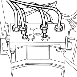
1. Using the specific tool, disconnect the rigid pipes at the hydraulic and electronic control unit.| Description | Code | Function | |
|---|---|---|---|
| - | key | 1.856.127.000 | Disconnect / connect the rigid pipes to the hydraulic and electronic control unit. |
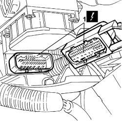
| Description | Connector | |
|---|---|---|
| 1 | ABS CONTROL UNIT | See M050 ABS CONTROL UNIT |
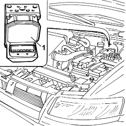
| Description | Connector | |
|---|---|---|
| - | ABS control unit | M50 |
| Description | Code | |
|---|---|---|
| - | Spanner | 1.856.127.000 |
| Fastening | Component | dia | Value(daNm) | |
|---|---|---|---|---|
| - | Male connector | RIGID FRONT BRAKE PIPE/ABS CONTROL UNIT | M12 x 1 | 1.4 |
| Description | Connector | |
|---|---|---|
| 1 | ABS control unit | M50 |
| Seal the threaded seats of the oil pipes. |


| Fastening | Component | dia | Value(daNm) | |
|---|---|---|---|---|
| - | Nut | HYDRAULIC AND ELECTRONIC CONTROL UNIT | M8 | 2.5 |
| The protection for the threaded seats should only be removed when the brake pipes are fitted to prevent any impurities from entering the control unit. |
| Fastening | Component | dia | Value(daNm) | |
|---|---|---|---|---|
| - | Male connector | RIGID FRONT BRAKE PIPE/ABS CONTROL UNIT | M10 | 1.6 |
| Fastening | Component | dia | Value(daNm) | |
|---|---|---|---|---|
| - | Male connector | RIGID FRONT BRAKE PIPE/ABS CONTROL UNIT | M10 | 1.6 |
| Fastening | Component | dia | Value(daNm) | |
|---|---|---|---|---|
| - | - | PIPE FROM PUMP TO HYDRAULIC CONTROL UNIT | M10 | 1.6 |
| Description | Connector | |
|---|---|---|
| - | ABS control unit | M50 |