3363714 - Introduction - ELECTRICAL CIRCUIT FOR INSTRUMENTS/INDICATORS
MINI F.L.Ore.N.C.E. ELECTRICAL AND ELECTRONIC SYSTEM
GENERAL CHARACTERISTICS
In conventional electrical systems, functions are activated with the aid of dedicated point-to-point connections.As the number of eletrical/electronic devices on board new vehicles has increased, the connection are becoming more complex and heavy. One reason for this is the complexity of functions implemented in the many electronic units, which require a continual interchange of data. All this makes it more difficult to install new electrical systems and increases the complexity of fault diagnosis.Many problems have been resolved and new electrical systems have been optimised compared to conventional systems by means of networking. This provides a more effective means of managing communication on board the car and for the transfer of information between subsystems via the serial buses present: single wires, pairs of twisted wires or even optical fibres. We shall now see how the move from conventional systems to those known as multiplexing has taken place.Classic solution
The four control units in the diagram below require a number (N) of wires for each input/output in order to perform their function. This has created so much wiring that the system is more complex (design and manufacture), more bulky (weight, bulk and cost) and requires some 40 kg of wiring harnesses amounting to a length of more than 2 km. This requirement is likely to double every 10 years because even now one such vehicle may be equipped with 20 to 40 control units (ECUs).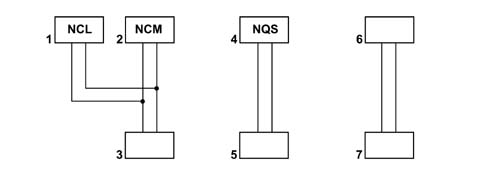
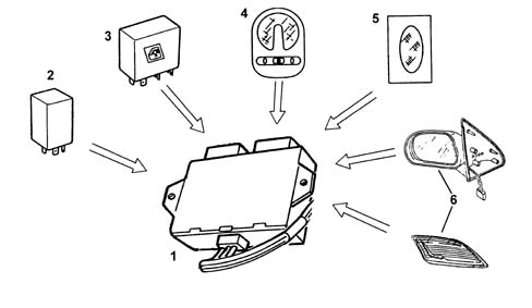
The integration of electrical/electronic functions in a single unit has allowed us to improve:
- the management of current consumption
- the functionality of appliances because they are managed by a single control unit;
- the fault diagnosis using control unit self-diagnosis
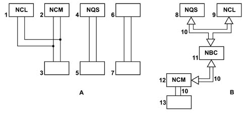
Multiplexing solution
This solution has made it possible to reduce the volume of cable looms and to considerably improve the transmission of information between the various electronic units.These transmissions take place through a BUS channel consisting of 2 cables (the main one already used for the telephone, radio, television network etc.)
In general, in order to send data via multiplexing, we need to define the following:
- (A) THE TRANSMISSION CHANNEL (electric cables, optical fibres, radio waves, etc.)
- (B) THE TYPE OF SIGNAL (voltage, current, light, etc.)
- (B) THE COMMUNICATION PROTOCOL (all the rules that allow management of analogue or digital transmission management, code type, address, transmission order, error recording etc.).
F.L.ORE.N.C.E STRUCTURE
The MINI F.L.ORE.N.C.E systemhas been designed for the optimum management of the vehicle's electrical and electronic functions.The system interacts with all the electrical system functions, directly cotnrolling the so-called bodywork functions (visibility, access, on board information, comfort, telematics, etc.) and supporting the exchange of data between the traction control systems (engine, braking, gearbox, etc.).For excellent performance each control unit (electronic or electro-mechanical) is located in a central position in relation to the functions which it manages. This allows minimisation of the power and signal distribution system through the extensive use of serial communication networks, with advantages when solving the problems of size, reliability, weight and cost.The distribution of power takes place via the junction units and/or fuse boxes, connected to the control elements (relays and static actuators) in order to ensure the maximum level of electrical protection and the minimum degree of wiring complexity . The ultrasound weld spots inside the vehicle wiring have been eliminated and replaced with short circuiting connections (already adopted on the Alf 147).The MINI FLORENCE system offers countless advantages such as, for example:
- the sensors in the various subsystems are made available to the network;
- information may be shared;
- similar sensors can be done away with;
- new functions can only be added by modifying the software (developed during the vehicle life),
- wiring design is simplified and the number of connectors is reduced,
- electronic device operating safety is increased to improve the reliability of information transmited,
- an integrated diagnostic function simplifies service operations on electric/electronic components.
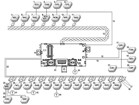
The system structure on the FIAT STILO comprises:
- 2 CAN communication NETWORKS which connect NODES (see note overleaf) belonging to two different areas: one for the dynamic control of the vehicle and one for the so-called 'bodywork' functions.
- 1 SERIAL LINE W for immobilizer recovery
- Different K SERIAL LINES for the fault diagnosis of several NODES / CONTROL UNITS
- 1 Serial line known as A - BUS
| NODES refer to all the electrical / electronic devices and control units which contain a specific interface (NETWORK INTERFACE) which makes it possible to transmit and receive data, information and signals which travel through CAN networks. |
| CAB | Air Bag Control Unit |
|---|---|
| CAV | Volumetric Alarm Control Unit |
| CBA | Battery Control Unit |
| CDC | CD-Changer |
| CER | Engine Cooling Fan Control Unit |
| CPD | Right Headlamp Control Unit |
| CPL | Dashboard Control Unit |
| CPP | Tyre Pressure Control Unit |
| CPS | Left Headlamp Control Unit |
| CSA | Anti-theft Alarm Control Unit |
| CSP | Rain/Dusk Sensor Control Unit |
| CTA | Sun Roof Control Unit |
| CVB | Luggage Compartment Control Unit (wiring at rear cable) |
| CVM | Engine Compartment Control Unit |
| CVS | Clock Spring Cable |
| DSP | Audio Hi-Fi Amplifier |
| NAC | Cruise Control Adaptive Node |
| NAG | Driving Geometry Node |
| NAP | Passenger Geometry Node |
| NAS | Steering Angle Sensor Node |
| NBC | Body Computer Node |
| NBS | Steering Lock Node |
| NCA | Automatic Transmission Node |
| NCL | Climate Control Node |
| NCM | Engine Control Node |
| NCR | Robotized Gearbox Node Interface |
| NFR | Braking System Node |
| NGE | Electrical Steering Node |
| ITN | Info Telematic Node |
| NPE | Passive Entry Node |
| NPG | Driver's Door Node |
| NPP | Passenger Door Node |
| NQS | Instrument Panel Node |
| NRR | Radio Receiver Node |
| NSC | Gear Selector Node |
| NSP | Parking Sensor Node |
| NVB | Luggage Compartment Node |
| NVO | Steering Wheel Node |
| SCS | Suspension Control Unit (Sky-Hook) |
The two C-CAN and B-CAN networks are physically separate from one another, but both meet at the BODY COMPUTER NODE; the latter, which is considered the MASTER node for the two networks, contains a GATEWAY function which allows the transfer of information/dat from one network to the other, even if the two networks are operating at different speeds:
- B-CAN NETWORK transmission speed = 50 Kbit/sec.
- C-CAN NETWORK transmission speed = 500 Kbit/sec.
| The fault diagnosis of the NODES connected to the B-CAN network is achieved via the CAN, whilst for those connected to the C-CAN require the specific K SERIAL LINES. The K lines and the B-CAN network meet in the connector for the EOBD fault diagnosis on the BODY COMPUTER. |
B - can network connection
The B - CAN network (low speed) on the FIAT STILO consists of 2 electrical cables, one White/Pink shown in the wiring diagram as a CAN - A cable and one Black/Pink one shown in| ... DATA ERROR - CROPPED TEXT | Ошибка данных - Текст обрезан ... |
|---|