194000271 - 1032A12 TIMING SYSTEM DRIVE CHAIN - R.R
| Description | Connector | |
|---|---|---|
| - | Battery | See A001 BATTERY |

| Description | Connector | |
|---|---|---|
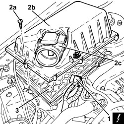
| 1 | Air flow meter | See K041 AIR FLOW METER |

| Follow the safety instructions and specific recommendations. |
| Tool | Description | Function | Validity |
|---|---|---|---|
| 2000002900 | Breather connector | Fuel system pressure drainage | 1.82.2 |
| Description | Connector | |
|---|---|---|
| 1 | Ignition coil | See A030 IGNITION COIL |

| Description | Connector | |
|---|---|---|
| 1 | Lambda sensor on catalyzer | See K017 LAMBDA SENSOR ON CATALYZER |
| Description | Connector | |
|---|---|---|
| 2 | Lambda sensor on catalyzer - 2 | See K018 LAMBDA SENSOR ON CATALYZER - 2 |

| Description | Connector | |
|---|---|---|
| 3 | Interference filter | See P087 NOISE FILTER |


| Tool | Description | Function | Validity |
|---|---|---|---|
| 1860815000 | Flange | Crankshaft rotation | 1.8 |


| Turn the hexagonal bolts on the camshafts using a fixed wrench to provide countertorque. |
| If necessary, turn the crankshaft slowly and gradually (in the direction of engine rotation). |
| Tool | Description | Function | Validity |
|---|---|---|---|
| 2000000900 | Template | Camshaft timing adjustment | 2.2 |


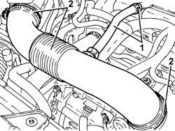
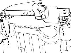
| Fasten the section of the exhaust pipe disconnected so that it is not hanging loose. The front section of the exhaust pipe including the flexible pipe can be fastened to the bodyshell appropriately using, for example metal wire.Bends in the flexible pipe at angles of between 5° and 10°, starting from the planned fitting position, can damage the flexible pipe. |


| Tool | Description | Function | Validity |
|---|---|---|---|
| 1820581000 | Crossmember | Power unit support | 1.82.2 |
| Tool | Description | Function | Validity |
|---|---|---|---|
| 1870650000 | Support blocks | Power unit support | 1.82.2 |
| Tool | Description | Function | Validity |
|---|---|---|---|
| 1860851003 | Crossmember | Power unit support | 1.82.2 |
| Tool | Description | Function | Validity |
|---|---|---|---|
| 1870748000 | Vertical support | Power unit support | 1.82.2 |


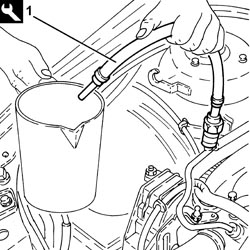
| Collect the engine oil in a suitable container. |
| Tool | Description | Function | Validity |
|---|---|---|---|
| 2000001000 | Counter-torque | Loosen/tighten crankshaft pulley fixing bolt | 2.2 |

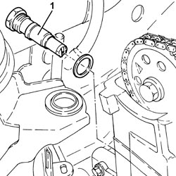
| Take care not to damage the sealing surfaces during destructive removal of the oil seal. |


| Secure the timing chain to prevent it falling. |
| Component | Fastening | dia | Value (daNm) | Validity |
|---|---|---|---|---|
| Timing moving chain tensioner pad | Bolt | M6 x 1 | (engine crankcase side) 1.0 | 2.2 |

| Component | Fastening | dia | Value (daNm) | Validity |
|---|---|---|---|---|
| Timing fixed chain tensioner pad | Lower bolt | M6 x 1 | (engine crankcase side) 1.0 | 2.2 |
| Component | Fastening | dia | Value (daNm) | Validity |
|---|---|---|---|---|
| Timing fixed chain tensioner pad | Upper bolt | M6 x 1 | (cylinder head side) 0.8 | 2.2 |

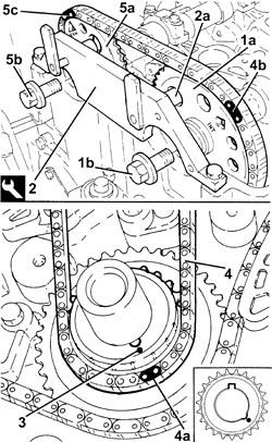
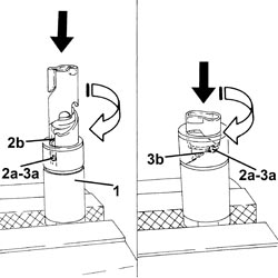
| Turn the intake side camshaft by means of the hexagon until timing tool pin (2a) fits into the hole on the pulley. |
| Tool | Description | Function | Validity |
|---|---|---|---|
| 2000000900 | Template | Camshaft timing adjustment | 2.2 |
| Turn the crankshaft slowly and steadily (in the direction of engine rotation). |
| Ensure the timing chain is not stuck. |
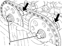
| The pink link (4a) should be aligned with the white notch stamped on the timing chain toothed drive pulley. |
| The bluel link (4b) must be aligned with the "INT" mark stamped on the intake side camshaft toothed drive pulley. |
| Turn the exhaust side camshaft by means of the hexagon until the pink link (5c) is aligned with the "EXH" mark stamped on the exhaust side toothed timing drive pulley. |
| Replace the o-rings. |
| Component | Fastening | dia | Value (daNm) | Validity |
|---|---|---|---|---|
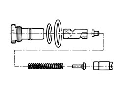
| Timing fixed hydraulic tensioner | - | M27 x 2 | 7.5 | 2.2 |
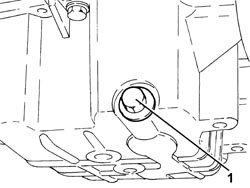
| Move the timing chain hydraulic tensioner to operating position by exercising overall pressure by hand on the chain in the area shown in the figure. This puts the chain under tension, which in turn acts on the mobile pad to release the mobile tensioner piston.When the tensioner piston is operated, the operating spring can be heard to click. |
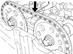
| If the chain remains slack, the tensioner is not in operating position. |
| When the crankshaft is turned, the tensioner piston should follow the chain through its rotation. |
| If they do not align, refit the timing chain without treating the coloured links on the chain as TDC reference points. |
| Tool | Description | Function | Validity |
|---|---|---|---|
| 2000000900 | Template | Camshaft timing adjustment | 2.2 |
| Component | Fastening | dia | Value (daNm) | Validity |
|---|---|---|---|---|
| Timing upper chain tensioner pad | Bolt (with thread-locking agent) | M6 x 1 | (cylinder head side) 1.0 | 2.2 |

| Turn the hexagonal bolts on the camshafts to provide countertorque. |
| Component | Fastening | dia | Value (daNm) | Validity |
|---|---|---|---|---|
| Camshaft toothed drive pullies | Bolt (to be replaced) | M12 x 1.75 | (camshaft side) 8.5 + 30° + 15° | 2.2 |
| Component | Fastening | dia | Value (daNm) | Validity |
|---|---|---|---|---|
| Spark plugs | - | M14 x 1.25 | (cylinder head side) 2.2 | 2.2 |

| Component | Fastening | dia | Value (daNm) | Validity |
|---|---|---|---|---|
| Crankshaft oil seal front cover | Bolt | M8 X 1.25 | (engine crankcase side) 2.1 | 2.2 |
| Replace the seal. |
| Component | Fastening | dia | Value (daNm) | Validity |
|---|---|---|---|---|
| Cap for timing fixed chain tensioner pad upper bolt | - | M22 x 1.5 | 6.5 | 2.2 |
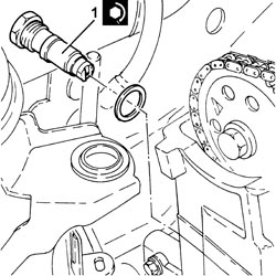
| Before fitting, slightly moisten the lip of the new oil seal. |
| Tool | Description | Function | Validity |
|---|---|---|---|
| 1860099000 | Fitting tool | Fitting flywheel side oil seal | 2.2 |

| Component | Fastening | dia | Value (daNm) | Validity |
|---|---|---|---|---|
| Services pulley on crankshaft | Bolt (to be replaced) | M14 X 1.5 | (engine crankshaft side) 10.0 +75° + 15° | 2.2 |
| Tool | Description | Function | Validity |
|---|---|---|---|
| 2000001000 | Counter-torque | Loosen/tighten crankshaft pulley fixing bolt | 2.2 |
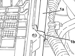
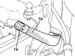
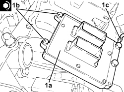
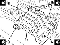
| Position the auxiliary drivebelt mobile tensioner so that the ridge (1c) on the tensioner fits into hole (1d). |
| Component | Fastening | dia | Value (daNm) | Validity |
|---|---|---|---|---|
| Engine components single belt moving tensioner | Bolt | M10 x 1.5 | (engine crankcase side) 4.3 | 2.2 |
| Component | Fastening | dia | Value (daNm) | Validity |
|---|---|---|---|---|
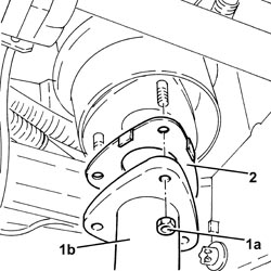
| Timing side power unit rigid support | Bolt | M12 x 1.75 | (engine crankcase side) 7.5 - 8.5 | 2.2 |
| Component | Fastening | dia | Value (daNm) | Validity |
|---|---|---|---|---|
| Timing side power unit rigid support flexible mounting | Bolt | M10 | (rigid support side) 5.0 - 6.0 | 1.82.21.9 JTD 16v1.9 JTD 8v |
| Component | Fastening | dia | Value (daNm) | Validity |
|---|---|---|---|---|
| Timing side power unit rigid support flexible mounting | Bolt | M10 | (bodyshell side) 5.0 - 6.0 |
| Component | Fastening | dia | Value (daNm) | Validity |
|---|---|---|---|---|
| Timing side power unit rigid support flexible mounting | Nut | M10 | (bodyshell side) 5.0 - 6.0 |
| Tool | Description | Function | Validity |
|---|---|---|---|
| 1820581000 | Crossmember | Power unit support | 1.82.2 |
| Tool | Description | Function | Validity |
|---|---|---|---|
| 1870650000 | Support blocks | Power unit support | 1.82.2 |
| Tool | Description | Function | Validity |
|---|---|---|---|
| 1860851003 | Crossmember | Power unit support | 1.82.2 |
| Tool | Description | Function | Validity |
|---|---|---|---|
| 1870748000 | Vertical support | Power unit support | 1.82.2 |
| Replace the seal. |
| Component | Fastening | dia | Value (daNm) | Validity |
|---|---|---|---|---|
| Engine oil drain plug | - | M12 x 1.75 | (oil sump side) 2.5 | 2.2 |

| Component | Fastening | dia | Value (daNm) | Validity |
|---|---|---|---|---|
| Flexible mounting for left side engine support | Bolt | M12 | (front suspension frame side) 7.5 ÷ 8.5 |

| Component | Fastening | dia | Value (daNm) | Validity |
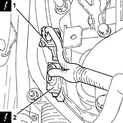
|---|---|---|---|---|
| Bracket on gearbox for lower reaction rod | Bolt | M12 | (gearbox side) 7.5 - 8.5 |
| Component | Fastening | dia | Value (daNm) | Validity |
|---|---|---|---|---|
| Lower reaction rod for gearbox | Bolt | M12 | (bracket side on gearbox) 7.5 - 8.5 |

| Component | Fastening | dia | Value (daNm) | Validity |
|---|---|---|---|---|
| Rigid pipe for exhaust pipe between catalytic converter and silencer | Nut (to replace) | M8 | (exhaust manifold with catalytic converter side) 1.6 | 2.2 |

| Tool | Description | Function | Validity |
|---|---|---|---|
| 1860815000 | Flange | Crankshaft rotation | 1.8 |
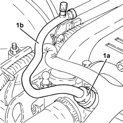
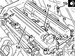
| Replace the o-rings (1c). |
| Component | Fastening | dia | Value (daNm) | Validity |
|---|---|---|---|---|
| Tappet cover | Bolt | M6 x 1 | (cylinder head side) 0.9 | 2.2 |
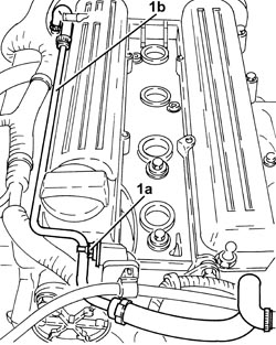
| Component | Fastening | dia | Value (daNm) | Validity |
|---|---|---|---|---|
| Ignition coil module | Bolt | M6 x 1 | (tappet cover side) 0.9 | 2.2 |

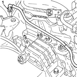
| Component | Fastening | dia | Value (daNm) | Validity |
|---|---|---|---|---|
| Front fuel supply pipe | Connector | - | (fuel manifold side) 1.0 | 2.2 |
