194000226 - 1004B10 POWER UNIT WITH MANUAL GEARBOX - R.R
| Description | Connector | |
|---|---|---|
| - | Battery | See A001 BATTERY |

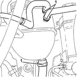
| Collect the coolant in a suitable container. |

| Collect the coolant that comes out in a suitable container. |


| Description | Connector | |
|---|---|---|
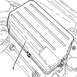
| 1 | Engine compartment junction unit | See B001 ENGINE COMPARTMENT JUNCTION UNIT |

| Description | Connector | |
|---|---|---|
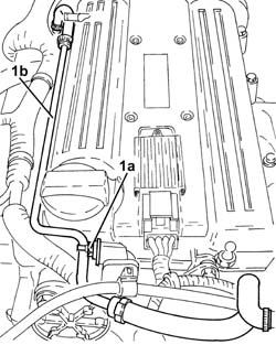
| 1b | Earth on engine | See C040 EARTH ON ENGINE |

| Description | Connector | |
|---|---|---|
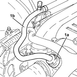
| 1b | Earth on engine | See C040 EARTH ON ENGINE |

| Description | Connector | |
|---|---|---|
| 1a | Engine fan motor | See N011 ELECTRIC FAN MOTOR |


| Description | Connector | |
|---|---|---|
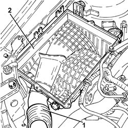
| 1 | Air flow meter | See K041 AIR FLOW METER |


| Follow the safety instructions and specific recommendations. |
| Tool | Description | Function | Validity |
|---|---|---|---|
| 2000002900 | Breather connector | Fuel system pressure drainage | 1.82.2 |

| Description | Connector | |
|---|---|---|
| 1 | 4 stage pressure switch | See K120 LINEAR SENSOR FOR FANS |
| Seal the connectors that have been disconnected using suitable plugs to prevent dampness and impurities from entering the system. |


| Tool | Description | Function | Validity |
|---|---|---|---|
| 2000001400 | Plug | Brake/clutch fluid reservoir cap |

| Tool | Description | Function | Validity |
|---|---|---|---|
| 1871001700 | Balance | Removing-refitting power unit |


| Component | Fastening | dia | Value (daNm) | Validity |
|---|---|---|---|---|
| Gearbox side power unit rigid support | Bolt | M10/12 | (gearbox side) 5.0 - 6.0 |

| Component | Fastening | dia | Value (daNm) | Validity |
|---|---|---|---|---|
| Timing side power unit rigid support flexible mounting | Bolt | M10 | (rigid support side) 5.0 - 6.0 | 1.82.21.9 JTD 16v1.9 JTD 8v |

| Tool | Description | Function | Validity |
|---|---|---|---|
| 2000001400 | Plug | Brake/clutch fluid reservoir cap |
| Replace any O-Rings for the connectors using green coloured seals only which are resistant to the R134a refrigerant fluid.Lubricate the connector threads using anti-freeze. |
| Component | Fastening | dia | Value (daNm) | Validity |
|---|---|---|---|---|
| AIR CONDITIONING PIPE TO CONDENSER | Nut | 1.6 ÷ 2.4 | 1.8 16v |
| Component | Fastening | dia | Value (daNm) | Validity |
|---|---|---|---|---|
| Front fuel supply pipe | Connector | - | (fuel manifold side) 1.0 | 2.2 |

| Component | Fastening | dia | Value (daNm) | Validity |
|---|---|---|---|---|
| Drain plug on water pump | - | M20 x 1.5 | (water pump side) 2.0 | 2.2 |