194000248 - 1016C10 SINGLE CYLINDER HEAD - R.R. AND REPLACE GASKET
| Description | Connector | |
|---|---|---|
| - | Battery | See A001 BATTERY |

| Description | Connector | |
|---|---|---|
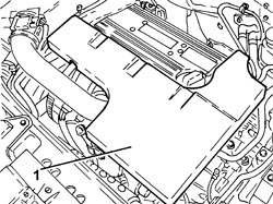
| 1 | Air flow meter | See K041 AIR FLOW METER |


| Follow the safety instructions and specific recommendations. |
| Tool | Description | Function | Validity |
|---|---|---|---|
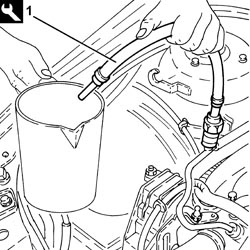
| 2000002900 | Breather connector | Fuel system pressure drainage | 1.82.2 |

| Description | Connector | |
|---|---|---|
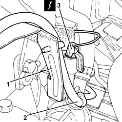
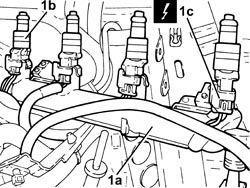
| 1 | Ignition coil | See A030 IGNITION COIL |


| Description | Connector | |
|---|---|---|
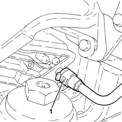
| 1 | Lambda sensor on catalyzer | See K017 LAMBDA SENSOR ON CATALYZER |
| Description | Connector | |
|---|---|---|
| 2 | Lambda sensor on catalyzer - 2 | See K018 LAMBDA SENSOR ON CATALYZER - 2 |


| Description | Connector | |
|---|---|---|
| 3 | Interference filter | See P087 NOISE FILTER |

| Description | Connector | |
|---|---|---|
| 1 | 4 stage pressure switch | See K010 4 STAGE PRESSURE SWITCH |

| Description | Connector | |
|---|---|---|
| 1 | Engine management control unit | See M010 ENGINE MANAGEMENT CONTROL UNIT |
| Description | Connector | |
|---|---|---|
| 2 | Engine coupling | See D029 ENGINE CABLES/ENGINE SERVICES CABLE COUPLING |


| Description | Connector | |
|---|---|---|
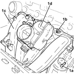
| 1c | Injector | See N070 INJECTOR |
| Description | Connector | |
|---|---|---|
| 1 | Integrated throttle casing actuator | See N075 INTEGRATED THROTTLE CASING ACTUATOR |
| Description | Connector | |
|---|---|---|
| 2 | Absolute pressure sensor | See K048 ABSOLUTE PRESSURE SENSOR |


| Collect the coolant that comes out in a suitable container. |


| Description | Connector | |
|---|---|---|
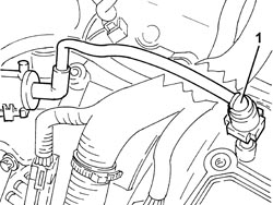
| 1 | Fuel vapour recovery solenoid valve | See L010 FUEL VAPOUR RECOVERY SOLENOID VALVE |

| Fasten the section of the exhaust pipe disconnected so that it is not hanging loose. The front section of the exhaust pipe including the flexible pipe can be fastened to the bodyshell appropriately using, for example metal wire.Bends in the flexible pipe at angles of between 5° and 10°, starting from the planned fitting position, can damage the flexible pipe. |

| Collect the coolant that comes out in a suitable container. |

| Collect the coolant in a suitable container. |


| Tool | Description | Function | Validity |
|---|---|---|---|
| 1871001700 | Balance | Removing-refitting power unit |


| Apply counter-torque to the camshafts. |

| Tool | Description | Function | Validity |
|---|---|---|---|
| 1871001700 | Balance | Removing-refitting power unit |

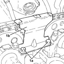
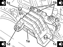
| One of the bolts also secures the earth lead. |
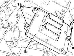
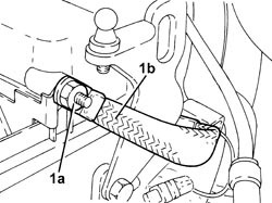
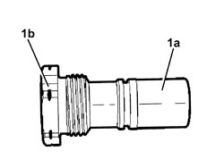
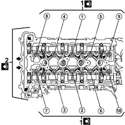
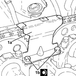
| The bolts (1b) are loosened first by 1/4 turn, then 1/2 a turn in the order illustrated in the diagram. |

| Two mechanics are needed for this operation.Take care to release the timing chain and the exhaust side camshaft drive pulley. |
| Measurement | Value | Validity | ||
|---|---|---|---|---|
| Cylinder head lower surface flatness (mm) | 0.05 | 1.82.2 16V | ||
| The gasket should be positioned with the word "TOP" facing upwards. |
| Two mechanics are needed for this operation.- Check that the centering bushes are correctly positioned.Take care to raise the timing chain and the exhaust side camshaft drive pulley. |
| Follow the order shown in the figure for each tightening sequence. |
| Component | Fastening | dia | Value (daNm) | Validity |
|---|---|---|---|---|
| Cylinder head | Bolt (to be replaced) | M11 x 1.5 | (engine crankcase side) 3.0 + 90° +60° +15° | 2.2 |
| Tool | Description | Function | Validity |
|---|---|---|---|
| 1860942000 | Torque wrench | Tighten bolts to torque plus angle |
| Component | Fastening | dia | Value (daNm) | Validity |
|---|---|---|---|---|
| Cylinder head | Timing side bolts (to replace) | M8 X 1.25 | (engine crankcase side) 3.5 | 2.2 |
| Tool | Description | Function | Validity |
|---|---|---|---|
| 1871001700 | Balance | Removing-refitting power unit |
| Component | Fastening | dia | Value (daNm) | Validity |
|---|---|---|---|---|
| Timing fixed chain tensioner pad | Upper bolt | M6 x 1 | (cylinder head side) 0.8 | 2.2 |
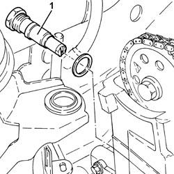
| Replace the seal. |
| Component | Fastening | dia | Value (daNm) | Validity |
|---|---|---|---|---|
| Cap for timing fixed chain tensioner pad upper bolt | - | M22 x 1.5 | 6.5 | 2.2 |

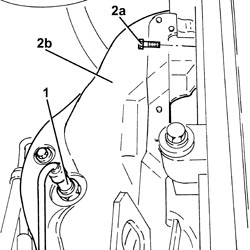
| Rotate the inlet side camshaft and insert the pin (2a) for the timing tool in the opening in the pulley. |
| Tool | Description | Function | Validity |
|---|---|---|---|
| 2000000900 | Template | Camshaft timing adjustment | 2.2 |
| Rotate the crankshaft slowly and evenly (in the direction of rotation of the engine). |
| Make sure that the timing chain is not stuck. |
| The light blue mesh (4a) should be in line with the "INT" mark stamped on the inlet side camshaft drive pulley. |
| Rotate the exhaust side camshaft until the pink mesh (5c) is in line with the "EXH" mark on the exhaust side camshaft drive pulley. |

| Replace the seals. |


| Component | Fastening | dia | Value (daNm) | Validity |
|---|---|---|---|---|
| Timing fixed hydraulic tensioner | - | M27 x 2 | 7.5 | 2.2 |

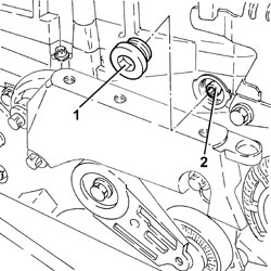
| Place the timing hydraulic tensioner in the operating position exerting manual pressure on the chain in the area shown in the diagram. This tensions the chain which, acting on the moving plate, allows the release of the moving tensioner piston.The operating spring is heard to make a "clack" noise when the tensioner piston is operated. |

| If the chain remains soft then the tensioner is not in the operating position. |
| When the crankshaft is rotated the tensioner piston should follow the chain during the rotation stage. |
| If they are not aligned, fit the timing chain again no longer taking any notice of the coloured chain meshes as T.D.C. references. |
| Tool | Description | Function | Validity |
|---|---|---|---|
| 2000000900 | Template | Camshaft timing adjustment | 2.2 |
| Component | Fastening | dia | Value (daNm) | Validity |
|---|---|---|---|---|
| Timing upper chain tensioner pad | Bolt (with thread-locking agent) | M6 x 1 | (cylinder head side) 1.0 | 2.2 |
| Apply counter-torque to the camshafts. |
| Component | Fastening | dia | Value (daNm) | Validity |
|---|---|---|---|---|
| Camshaft toothed drive pullies | Bolt (to be replaced) | M12 x 1.75 | (camshaft side) 8.5 + 30° + 15° | 2.2 |

| Component | Fastening | dia | Value (daNm) | Validity |
|---|---|---|---|---|
| Spark plugs | - | M14 x 1.25 | (cylinder head side) 2.2 | 2.2 |
| Component | Fastening | dia | Value (daNm) | Validity |
|---|---|---|---|---|
| Timing side power unit rigid support flexible mounting | Bolt | M10 | (rigid support side) 5.0 - 6.0 | 1.82.21.9 JTD 16v1.9 JTD 8v |
| Component | Fastening | dia | Value (daNm) | Validity |
|---|---|---|---|---|
| Timing side power unit rigid support flexible mounting | Bolt | M10 | (bodyshell side) 5.0 - 6.0 |
| Component | Fastening | dia | Value (daNm) | Validity |
|---|---|---|---|---|
| Timing side power unit rigid support flexible mounting | Nut | M10 | (bodyshell side) 5.0 - 6.0 |
| Tool | Description | Function | Validity |
|---|---|---|---|
| 1871001700 | Balance | Removing-refitting power unit |
| Component | Fastening | dia | Value (daNm) | Validity |
|---|---|---|---|---|
| Air chamber | Nut | M6 x 1 | (cylinder head side) 0.9 | 2.2 |
| Component | Fastening | dia | Value (daNm) | Validity |
|---|---|---|---|---|
| Air chamber | Bolt | M6 x 1 | (cylinder head side) 0.9 | 2.2 |

| One of the bolts also secures the earth lead (1c). |
| Component | Fastening | dia | Value (daNm) | Validity |
|---|---|---|---|---|
| Injection/ignition system control unit | Bolt | M6 x 1 | (air chamber side) 0.9 | 2.2 |

| Component | Fastening | dia | Value (daNm) | Validity |
|---|---|---|---|---|
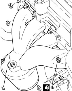
| Exhaust manifold with catalytic converter | Nut (to replace) | - | (cylinder head side) 2.0 | 1.82.2 |
| Component | Fastening | dia | Value (daNm) | Validity |
|---|---|---|---|---|
| Front Lambda sensor to catalytic converter | - (with special black grease) | M18 x 1.5 | (exhaust manifold with catalytic converter side) 4.0 | 2.2 |

| Tool | Description | Function | Validity |
|---|---|---|---|
| 1871001700 | Balance | Removing-refitting power unit |
| Apply sealant to the plug before fitting it. |
| Component | Fastening | dia | Value (daNm) | Validity |
|---|---|---|---|---|
| Drain plug on water pump | - | M20 x 1.5 | (water pump side) 2.0 | 2.2 |

| Component | Fastening | dia | Value (daNm) | Validity |
|---|---|---|---|---|
| Rigid pipe for exhaust pipe between catalytic converter and silencer | Nut (to replace) | M8 | (exhaust manifold with catalytic converter side) 1.6 | 2.2 |

| Component | Fastening | dia | Value (daNm) | Validity |
|---|---|---|---|---|
| Fuel manifold pipe | Bolt | M6 x 1 | (cylinder head side) 0.9 | 2.2 |
| Replace the seals (1c). |
| Component | Fastening | dia | Value (daNm) | Validity |
|---|---|---|---|---|
| Tappet cover | Bolt | M6 x 1 | (cylinder head side) 0.9 | 2.2 |

| Component | Fastening | dia | Value (daNm) | Validity |
|---|---|---|---|---|
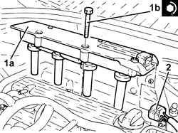
| Ignition coil module | Bolt | M6 x 1 | (tappet cover side) 0.9 | 2.2 |
| Component | Fastening | dia | Value (daNm) | Validity |
|---|---|---|---|---|
| Front fuel supply pipe | Connector | - | (fuel manifold side) 1.0 | 2.2 |
