194000401 - 1088C10 WATER PUMP - R + R

Removing
(
Refitting
)
- Position the vehicle on a lift.- Make sure that the ignition key is in the OFF position, then disconnect the battery terminal (-).1. Remove the sound insulation cover fastened to the engine by three pins.
1. Disconnect the electrical connection for the front Lambda sensor to the catalytic converter.2. Disconnect the electrical connection for the rear Lambda sensor to the catalytic converter.3. Undo the fastenings and remove the eletrical connections mounting bracket.
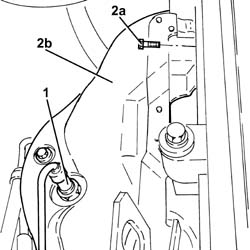
1. Undo the front Lambda sensor from the catalytic converter and remove it.2. Undo the bolts (2a) and remove the heat shield (2b).
Op. 4450B04 RIGHT FRONT WHEEL - R.R Op. 7055B66 ENGINE COMPARTMENT DUST COVER IN RIGHT FRONT WHEEL ARCH - R.R.1. Undo the coolant drain plug in the water pump and drain the coolant. | Collect the coolant in a suitable container. |
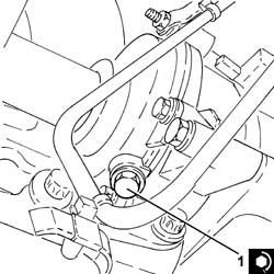
1. Disconnect the electrical connection from the engine coolant temperature sensor.2. Loosen the collar and disconnect the upper coolant input sleeve to the radiator, thermostat side.3. Loosen the bands and disconnect the coolant delivery and return pipes to the climate control system heater, thermostat side.4. Undo the engine coolant temperature sensor and remove it. | The engine coolant temperature sensor is removed to gain access to one of the thermostat fixing bolts. |
5. Undo the bolts (5a) and remove the thermostat (5b) complete with water pump rigid fluid inlet pipe (5c) and O-rings (5d).
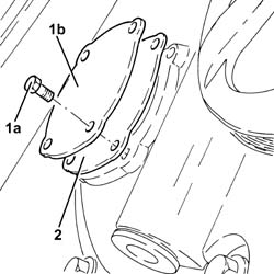
1. Loosen the nut fixing the electric wiring mounting bracket.2. Undo the bolts (2a) and remove the water pump cover (2b), complete with seal.
1. Undo the bolts (1a) and remove the water pump service cover (1b) from the timing chain cover.2. Remove the gasket.
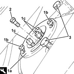
1. Fit the tool (1a) for securing the water pump drive pulley and fasten with two bolts (1b) to the timing chain cover and with three bolts (1c) to the water pump drive pulley.| Tool | Description | Function | Validity |
|---|
| 2000001200 | Flange | Securing water pump pulley | 2.2 |
2. Undo the three bolts fixing the drive pulley to the water pump.3. Undo the two bolts fixing the water pump to the engine block. | The lower bolt should not be extracted on account of its length. |
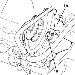
1. Undo the remaining bolt (1a) and remove the water pump (1b) complete with O-ring.
Refitting
(
Removing
)
-Clean the surfaces of the water pump.- Place the water pump, complete with new O-ring in its housing and secure it tightening the bolts to the recommended torque. | Apply (white) silicon grease to the O-ring.Take care to align the drive gear with the water pump. |
| Component | Fastening | dia | Value (daNm) | Validity |
|---|
| Water pump | Bolt | M8 X 1.25 | (engine crankcase side) 2.3 | 2.2 |
- Tighten the bolts fixing the drive pulley to the water pump to the recommended torque.| Component | Fastening | dia | Value (daNm) | Validity |
|---|
| Water pump drive pulley | Bolt | M6 x 1 | (water pump side) 0.8 | 2.2 |
- Remove the tool used for securing the water pump drive pulley.| Tool | Description | Function | Validity |
|---|
| 2000001200 | Flange | Securing water pump pulley | 2.2 |
1. Place the water pump cover (1a), complete with a new seal, back in its housing and secure it tightening the bolts (1b) to the recommended torque. | Apply (white) silicon grease to the seal. |
| Pay attention to the centering bushes. |
| Component | Fastening | dia | Value (daNm) | Validity |
|---|
| Water pump cover | Bolt | M6 x 1 | (water pump side) 0.8 | 2.2 |
2. Tighten the nut fixing the electric wiring mounting bracket.
1. Tighten the coolant drain plug to the water pump to the recommended torque. | Apply sealant to the plug before fitting it. |
| Component | Fastening | dia | Value (daNm) | Validity |
|---|
| Drain plug on water pump | - | M20 x 1.5 | (water pump side) 2.0 | 2.2 |
1. Place the water pump service cover (1a), complete with a new gasket, back in its housing and secure it tightening the bolts (1b) to the recommended torque.| Component | Fastening | dia | Value (daNm) | Validity |
|---|
| Water pump service cover | Bolt | M6 x 1 | (side) 0.7 | 2.2 |
1. Place the thermostat (1a) complete with water pump rigid coolant inlet pipe (1b) and new O-rings (1c) back in its housing and secure it tightening the bolts (1d) to the recommended torque.| Component | Fastening | dia | Value (daNm) | Validity |
|---|
| Thermostat unit | Bolt | M6 x 1 | (engine crankcase side) 0.6 - 1.0 | 2.2 |
2. Place the engine coolant temperature sensor in its housing and tighten it to the recommended torque.| Component | Fastening | dia | Value (daNm) | Validity |
|---|
| Engine coolant temperature sensor | - | M12 x 1.5 | (thermostat unit side) 2.1 | 2.2 |
3. Connect the coolant delivery and return pipes to the climate control system heater, thermostat side, and tighten the band.
4. Connect the upper coolant input sleeve to the radiator, thermostat side, and tighten the band.5. Connect the electrical connection to the engine coolant temperature sensor.
Op. 7055B66 ENGINE COMPARTMENT DUST COVER IN RIGHT FRONT WHEEL ARCH - R.R. Op. 4450B04 RIGHT FRONT WHEEL - R.R- Place the heat shield back in its housing and secure it using the bolts.- Position the front Lambda sensor in its housing and tighten it to the recommended torque.| Component | Fastening | dia | Value (daNm) | Validity |
|---|
| Front Lambda sensor to catalytic converter | - (with special black grease) | M18 x 1.5 | (exhaust manifold with catalytic converter side) 4.0 | 2.2 |
- Place the electrical connections mounting bracket in its housing and secure it.- Connect the electrical connection for the rear Lambda sensor to the catalytic converter.- Connect the electrical connection for the front Lambda sensor to the catalytic converter.- Place the sound insulation cover back in its housing and secure it to the engine using the three pins.- Connect the negative battery terminal. Op. 0010T20 ENGINE COOLANT - CHANGE- Remove the vehicle from the lift.