194000418 - 1092B92 WATER PUMP /BALANCING SHAFT DRIVE CHAIN HYDRAULIC TENSIONER R R
| Description | Connector | |
|---|---|---|
| - | Battery | See A001 BATTERY |
| Description | Connector | |
|---|---|---|
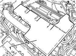
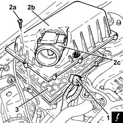
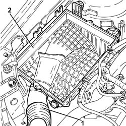
| 1 | Air flow meter | See K041 AIR FLOW METER |
| Follow the safety instructions and specific recommendations. |
| Tool | Description | Function | Validity |
|---|---|---|---|
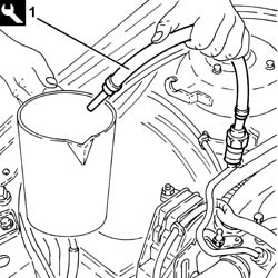
| 2000002900 | Breather connector | Fuel system pressure drainage | 1.82.2 |
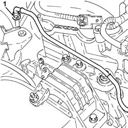
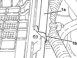
| Fasten the section of the exhaust pipe disconnected so that it is not hanging loose. The front section of the exhaust pipe including the flexible pipe can be fastened to the bodyshell appropriately using, for example metal wire.Bends in the flexible pipe at angles of between 5° and 10°, starting from the planned fitting position, can damage the flexible pipe. |
| Tool | Description | Function | Validity |
|---|---|---|---|
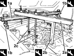
| 1820581000 | Crossmember | Power unit support | 1.82.2 |
| Tool | Description | Function | Validity |
|---|---|---|---|
| 1870650000 | Support blocks | Power unit support | 1.82.2 |
| Tool | Description | Function | Validity |
|---|---|---|---|
| 1860851003 | Crossmember | Power unit support | 1.82.2 |
| Tool | Description | Function | Validity |
|---|---|---|---|
| 1870748000 | Vertical support | Power unit support | 1.82.2 |
| Collect the engine oil in a suitable container. |
| Tool | Description | Function | Validity |
|---|---|---|---|
| 2000001000 | Counter-torque | Loosen/tighten crankshaft pulley fixing bolt | 2.2 |
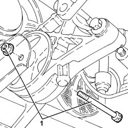
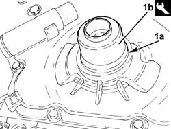
| Take care not to damage the sealing surfaces during the "destructive" removal of the oil seal. |
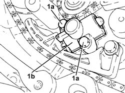
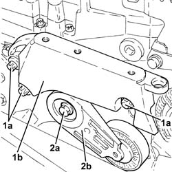
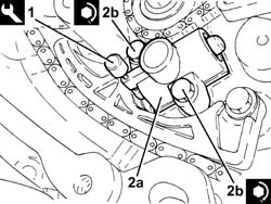
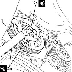
| Press the tensioner piston and turn to the right to fit the tool. |
| Component | Fastening | dia | Value (daNm) | Validity |
|---|---|---|---|---|
| Water pump/balancing shafts drive chain hydraulic tensioner | Bolt | M6 x 1 | (engine crankcase side) 1.0 | 2.2 |
| Component | Fastening | dia | Value (daNm) | Validity |
|---|---|---|---|---|
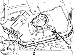
| Crankshaft oil seal front cover | Bolt | M8 X 1.25 | (engine crankcase side) 2.1 | 2.2 |
| Before installation, spread the lip of the new seal lightly with white silicone grease. |
| Tool | Description | Function | Validity |
|---|---|---|---|
| 1860099000 | Fitting tool | Fitting flywheel side oil seal | 2.2 |
| Component | Fastening | dia | Value (daNm) | Validity |
|---|---|---|---|---|
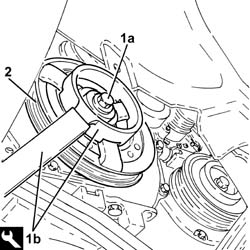
| Services pulley on crankshaft | Bolt (to be replaced) | M14 X 1.5 | (engine crankshaft side) 10.0 +75° + 15° | 2.2 |
| Tool | Description | Function | Validity |
|---|---|---|---|
| 2000001000 | Counter-torque | Loosen/tighten crankshaft pulley fixing bolt | 2.2 |
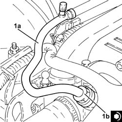
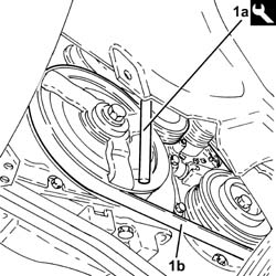
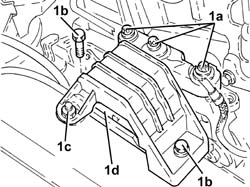
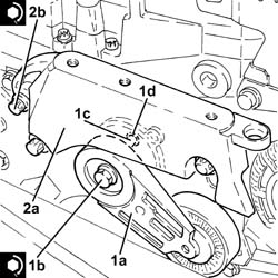
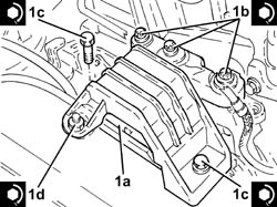
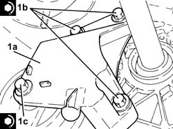
| Position the auxiliary drivebelt mobile tensioner so that the ridge (1c) on the tensioner fits into hole (1d). |
| Component | Fastening | dia | Value (daNm) | Validity |
|---|---|---|---|---|
| Engine components single belt moving tensioner | Bolt | M10 x 1.5 | (engine crankcase side) 4.3 | 2.2 |
| Component | Fastening | dia | Value (daNm) | Validity |
|---|---|---|---|---|
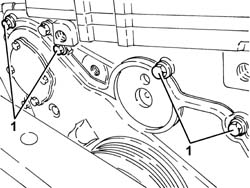
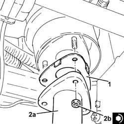
| Timing side power unit rigid support | Bolt | M12 x 1.75 | (engine crankcase side) 7.5 - 8.5 | 2.2 |
| Component | Fastening | dia | Value (daNm) | Validity |
|---|---|---|---|---|
| Timing side power unit rigid support flexible mounting | Bolt | M10 | (rigid support side) 5.0 - 6.0 | 1.82.21.9 JTD 16v1.9 JTD 8v |
| Component | Fastening | dia | Value (daNm) | Validity |
|---|---|---|---|---|
| Timing side power unit rigid support flexible mounting | Bolt | M10 | (bodyshell side) 5.0 - 6.0 |
| Component | Fastening | dia | Value (daNm) | Validity |
|---|---|---|---|---|
| Timing side power unit rigid support flexible mounting | Nut | M10 | (bodyshell side) 5.0 - 6.0 |
| Tool | Description | Function | Validity |
|---|---|---|---|
| 1820581000 | Crossmember | Power unit support | 1.82.2 |
| Tool | Description | Function | Validity |
|---|---|---|---|
| 1870650000 | Support blocks | Power unit support | 1.82.2 |
| Tool | Description | Function | Validity |
|---|---|---|---|
| 1860851003 | Crossmember | Power unit support | 1.82.2 |
| Tool | Description | Function | Validity |
|---|---|---|---|
| 1870748000 | Vertical support | Power unit support | 1.82.2 |
| Component | Fastening | dia | Value (daNm) | Validity |
|---|---|---|---|---|
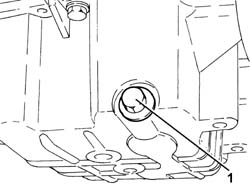
| Engine oil drain plug | - | M12 x 1.75 | (oil sump side) 2.5 | 2.2 |
| Component | Fastening | dia | Value (daNm) | Validity |
|---|---|---|---|---|
| Flexible mounting for left side engine support | Bolt | M12 | (front suspension frame side) 7.5 ÷ 8.5 |
| Component | Fastening | dia | Value (daNm) | Validity |
|---|---|---|---|---|
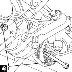
| Bracket on gearbox for lower reaction rod | Bolt | M12 | (gearbox side) 7.5 - 8.5 |
| Component | Fastening | dia | Value (daNm) | Validity |
|---|---|---|---|---|
| Lower reaction rod for gearbox | Bolt | M12 | (bracket side on gearbox) 7.5 - 8.5 |
| Component | Fastening | dia | Value (daNm) | Validity |
|---|---|---|---|---|
| Rigid pipe for exhaust pipe between catalytic converter and silencer | Nut (to replace) | M8 | (exhaust manifold with catalytic converter side) 1.6 | 2.2 |
| Component | Fastening | dia | Value (daNm) | Validity |
|---|---|---|---|---|
| Front fuel supply pipe | Connector | - | (fuel manifold side) 1.0 | 2.2 |