194000714 - 5530A10 ALTERNATOR - R+R
| Description | Connector | |
|---|---|---|
| - | Battery | See A001 BATTERY |


| Description | Connector | |
|---|---|---|
| 1 | Air flow meter | See K041 AIR FLOW METER |


| Description | Connector | |
|---|---|---|
| 1 | Engine management control unit | See M010 ENGINE MANAGEMENT CONTROL UNIT |
| One of the bolts also secures the earth lead. |

| Description | Connector | |
|---|---|---|
| 1 | Engine cables/engine services cable coupling | See D029 ENGINE CABLES/ENGINE SERVICES CABLE COUPLING |

| Tool | Description | Function | Validity |
|---|---|---|---|
| 1860815000 | Flange | Crankshaft rotation | 1.8 |

| Collect the engine coolant in a suitable container. |


| Description | Connector | |
|---|---|---|
| 1 | Fuel vapour recovery solenoid valve | See L010 FUEL VAPOUR RECOVERY SOLENOID VALVE |


| Description | Connector | |
|---|---|---|
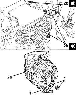
| 2 | Alternator | See A010 ALTERNATOR |

| Component | Fastening | dia | Value (daNm) | Validity |
|---|---|---|---|---|
| Alternator | Bolt | M8 | (engine crankcase side) 2.3 - 2.8 | 2.2 |
| Tool | Description | Function | Validity |
|---|---|---|---|
| 1860815000 | Flange | Crankshaft rotation | 1.8 |
| One of the bolts also secures the earth lead (1c). |
| Component | Fastening | dia | Value (daNm) | Validity |
|---|---|---|---|---|
| Injection/ignition system control unit | Bolt | M6 x 1 | (air chamber side) 0.9 | 2.2 |
