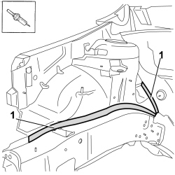
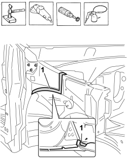
1. Use a hot air blower and a wire brush to remove the sealant and underbody protection.
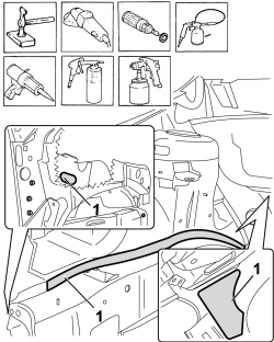
1. Use a hot air blower and a wire brush to remove the sealant and underbody protection.
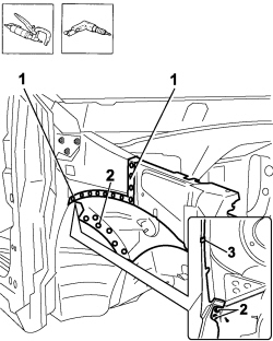
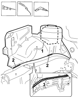
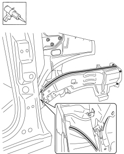
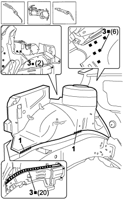
1. Use the chamfering machine to remove the spot welds shown in the diagram.2. Use the drill and chamfer the spot welds not accessible with the chamfering machine.3. Open the fastening clip.
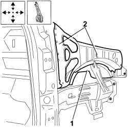
1. Use an alternating saw following the dotted cutting lines shown in he diagram to access the weld spots inside the turret.2. Use an oxyacetylene torch and wire brush to unsolder the brazing shown in the diagram.3. Use the drill and chamfer the spot welds not accessible with the chamfering machine.
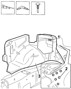
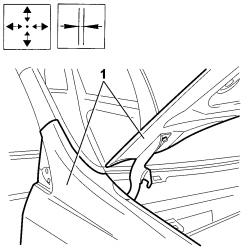
1. Use the drill and chamfer the spot welds inside the turret shown in the diagram.2. Use the drill and chamfer the spot welds in the windscreen wiper compartment shown in the diagram.- Use the hammer and chisel and remove the spot welds chamfered previously.3. Remove the shock absorber mounting turret.
- Straighten the edges of the bodyshell using a hammer and dolly block.- Remove the spot weld residues using a disc grinder.- Use a rotary brush to clean the areas treated previously.1. Apply electro-galvanizing paint.
1. Work at the bench and make the openings shown in the diagram in the replacement turret using a drill.- Remove the anti-corrosion treatment from the entire perimeter of the replacement reinforcement using a rotary brush on both the inside and the outside.2. Apply electro-weldable paint to the edges treated previously.
Refitting
(
Removing
)
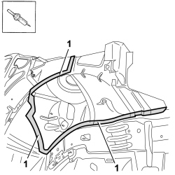
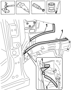
- Apply sealant to the areas illustrated in the diagram.
1. Position the front shock absorber mounting turret correctly on the vehicle and secure it using self-locking clamps and later on using parker bolts.2. Position the side panel outer front reinforcement and the upper front strut correctly on the vehicle. Secure them using self-locking clamps and then using Parker bolts.
1. Fit the wing and the bonnet provisionally.- Check the alignment and the surrounding gaps.
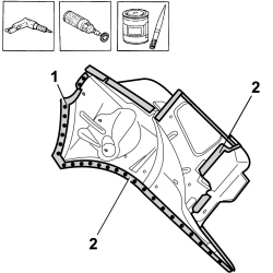
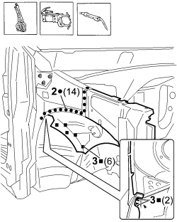
1. Close the fastening clip.2. Use a spot welder in the areas shown in the diagram.3. Use the MIG welder to fill weld at the points shown in the diagram.
1. Use the oxyacetylene torch and braze the points shown in the diagram.2. Use a spot welder in the areas shown in the diagram.3. Use the MIG welder to fill weld at the points shown in the diagram.
- Correct any distortions to the panel using a hammer and dolly block.- Use a disc grinder to level and remove the welding.- Use a rotary brush to clean the areas welded previously.1. Apply anti-oxidant protection to the areas involved in the welding.
- Correct any distortions to the panel using a hammer and dolly block.- Use a disc grinder to level and remove the welding.- Use a rotary brush to clean the areas welded previously.1. Apply anti-oxidant protection to the areas involved in the welding.- Seal the join lines between the replacement part and the vehicle.- Apply the underbody protection.- Renew the sound insulation.- Proceed with the painting stage.