194002124 - 1004E20 ENGINE - DISMANTLE AND REASSEMBLE FOLLOWING OPERATION 1004E10 - WASH AND CHECK DISMANTLED PARTS - REFIT CYLINDER HEAD AND OIL SUMP - DOES NOT INCLUDE REPAIRS TO CYLINDER HEAD AND AUXILIARY UNIT

Removing
(
Refitting
)
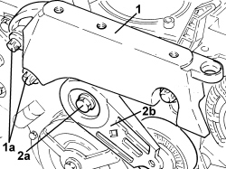
1. Undo the bolts (1a) and remove the rigid power unit support (1b).2. Undo the bolt (2a) and remove the auxiliary unit drive belt (2b).
1. Undo the bolt (1a) using the tool (1b) for counter-torque and remove the crankshaft pulley (1c).| Tool | Description | Function | Validity |
|---|
| 2000001000 | Counter-torque | Loosen/tighten crankshaft pulley fixing bolt | 2.2 |
2. Undo the bolts (2a) and remove the timing chain cover (2b).- Remove the gasket.
1. Undo the bolt (1a) and remove the timing chain fixed pad (1b).
1. Undo the bolt (1a) and remove the moving pad (1b) and the timing chain (1c).
1. Release the timing chain toothed wheel.2. Undo the bolt (2a) and remove the timing chain (2b) lubrication jet.
1. Undo the bolts (1a) and remove the counter-balance shaft chain hydraulic belt tensioner (1b).
1. Undo the bolts (1a) and remove the three counter-balance shaft chain pads (1b).2. Remove the counter-balance shaft chain.3. Release the counter-balance shaft chain toothed wheel.
1. Undo the bolts (1a) and remove the two counter-balance shafts (1b). | The inlet side counter-balance shaft has a green paint mark and the exhaust side one has a white paint mark. |
1. Undo the bolts (1a) and remove the water pump gear (1b).
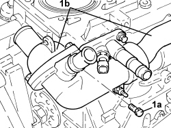
1. Undo the fastenings (1a) and remove the thermostat complete with coolant temperature sensor and rigid supply pipe to the water pump (1b).
1. Undo the fastenings (1a) and remove the water pump cover (1b).
1. Undo the bolts (1a) and remove the pump casing (1b).
1. Undo the bolts (1a) and remove the intermediate shaft support (1b).
1. Undo bolts (1a) and remove alternator (1b).
1. Undo the bolts (1a) and remove the starter motor (1b).2. Undo the bolt (2a) and remove the rpm sensor (2b).3. Undo the bolt (3a) and remove the detonation sensor (3b).4. Undo and remove the engine oil pressure warning light switch.
1. Undo and remove the engine oil filter cartridge cap.
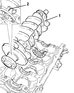
- Check that the crankshaft endfloat corresponds to the recommended figures using a magnetic base and dial gauge.| Measurement | Value | Validity |
|---|
| Crankshaft endfloat (mm) | 0.092 ÷ 0.240 | 2.2 16V |
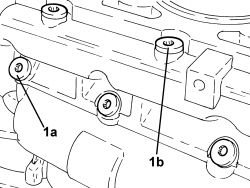
1. Undo the outer bolts (1a), undo the double row of inner bolts (1b) and remove the sealant at the two preset points (1c) and remove the panel under the crankcase (1d).
| Pay attention to the fitting position of the panel under the crankcase. |
- Remove the flywheel side crankshaft seal.
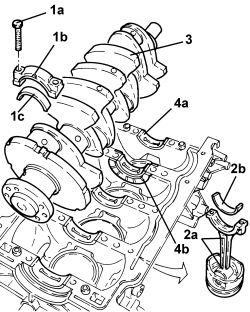
1. Undo the bolts (1a) and remove the connecting rod caps (1b) and half-bearings (1c).2. Remove the piston-connecting rod assemblies (2a) complete with half-bearings (2b). | Mark the connecting rod and cap and pay attention to the cylinder sequence. The breaking surfaces of the connecting rod and the cap match individually and therefore cannot be swapped or damaged. Do not exert pressure to the breaking surfaces. |
3. Remove the crankshaft.4. Remove the crankshaft half bearings (4a) and the thrust washers (4b).- Remove the locating bushes for the cylinder block/crankcase.
1. Undo the engine oil duct plugs (1a) and the water duct plugs (1b).
Refitting
(
Removing
)
- Wash all the dismantled components thoroughly.- Clean the matching surfaces between the oil sump and the panel under the crankcase and between the panel under the crankcase and the crankcase.- Refit the threaded plugs for the water and engine oil ducts.- Lubricate all the mechanical components with engine oil.- Visually check that the cylinder head support surface does not have cracks or superficial grooves.- Check that the internal diameter of the cylinder liners is within the recommended limits.| Measurement | Value | Validity |
|---|
| Cylinder liner bore | 85.992 - 86.008 mm | 2.2 16V |
| Measurement | Value | Validity |
|---|
| Cylinder liner oversize | 86.117 - 86.133 mm | 2.2 16V |
- Check that the diameter of the main journals corresponds to the recommended figures.| Measurement | Value | Validity |
|---|
| Main journal diameter (mm) | 55.994 ÷ 56.008 | 2.2 16V |
- Check that the diameter of the crankpins corresponds to the recommended figures.| Measurement | Value | Validity |
|---|
| Crankpin diameter (mm) | 49.000 ÷ 49.014 | 2.2 16V |
- Check the matching between the gudgeon pin and the housing in the piston; it should be possible to insert the pin simply by pressing and it should not slip out. Check that the outer diameter of the gudgeon pins is within the recommended limits; if not, replace the worn gudgeon pins.| Measurement | Value | Validity |
|---|
| Gudgeon pin outer diameter (mm) | 19.995 ÷ 20.000 | 2.2 16V |
- Fit the piston rings in the cylinder bore and check that the opening between the ends is within the recommended values; if this is not the case, replace the circlips.| Measurement | Value | Validity |
|---|
| Cylinder compression 1st piston ring gap (mm) | 0.20 ÷ 0.40 | 2.2 16V |
| Measurement | Value | Validity |
|---|
| Cylinder compression 2nd piston ring gap (mm) | 0.35 ÷ 0.55 | 2.2 16V |
| Measurement | Value | Validity |
|---|
| Oil scraper ring endfloat (mm) | 0.20 ÷ 0.35 | 1.8 |
- The size of the seals is given below.| Measurement | Value | Validity |
|---|
| Cylinder compression 1st piston ring thickness (mm) | 1.17 ÷ 1.19 | 2.2 16V |
| Measurement | Value | Validity |
|---|
| Cylinder compression 2nd piston ring thickness (mm) | 1.47 ÷ 1.49 | 2.2 16V |
| Measurement | Value | Validity |
|---|
| Piston oil scraper ring size (mm) | 2.348 ÷ 2.477 | 2.2 16V |
- Check that the outer diameter of the pistons corresponds to the recommended figures; if not, replace the piston complete with piston rings and gudgeon pin.| Measurement | Value | Validity |
|---|
| Piston outer diameter (mm) | 85.967 ÷ 85.982 | 2.2 16V |
- The clearance between the pistons and the liner/bore is given below.| Measurement | Value | Validity |
|---|
| Clearance between piston - cylinder liner/bore (mm) | 0.025 ÷ 0.026 | 2.2 16V |
- Check that the endfloat between the seals and the housings in the piston is within the recommended values; if this is not the case, replace the seals with oversize ones.| Measurement | Value | Validity |
|---|
| Cylinder compression 1st piston ring endfloat (mm) | 0.06 | 2.2 16V |
| Measurement | Value | Validity |
|---|
| Cylinder compression 2nd piston ring endfloat (mm) | 0.05 | 2.2 16V |
| Measurement | Value | Validity |
|---|
| Oil scraper ring endfloat (mm) | 0.063 ÷ 0.172 | 2.2 16V |
- Check the main half bearings, noting that the half-bearings should not be adapted. Replace them if scoring or signs of binding are noted.- Fit the main bearing halves in their seats on the upper crankcase, aligning the lubrication holes and ensuring scrupulous cleanliness. The centre crankshaft bearing has thrust half-washers incorporated becuase it acts as a thrust carrier.- If the crankshaft has been ground, fit new oversize half-bearings to restore the initial tolerance conditions.1. Place the crankshaft in its housing.2. Fit the calibrated wire for measuring the bearing clearance.
- Fit the main journal half-bearings in the lower cylinder block/crankcase.1. Fit the lower crankcase on the upper one.2. Tighten bolts (2a) and bolts (2b) securing the lower crankcase.| Component | Fastening | dia | Value (daNm) | Validity |
|---|
| Lower engine crankcase | Bolt | M8 X 1.25 | (outer side) 2.3 | 2.2 |
| Component | Fastening | dia | Value (daNm) | Validity |
|---|
| Lower engine crankcase | Bolt | M10 x 1.5 | (inner side) 2.0 +70° +15° | 2.2 |
- Bolt tightening sequence (I = M10; II = M8)
1. Remove the lower crankcase and check the crankpin clearance. Use an appropriate gauge to measure the width of the plastigage. | Check one main journal at a time, without rotating the crankshaft. |
| Measurement | Value | Validity |
|---|
| Clearance between main bearings - crankshaft bearings (mm) | 0.007 ÷ 0.014 | 2.2 16V |
- After having checked all the main journals, apply a bead of sealant about 2 - 5 mm thick in the splining in the crankcase and then proceed with the definitive fitting of the lower crankcase tightening the bolts to torque following the order given previously.- Fit the flywheel side crankshaft seal.- Rotate the engine through 180° on the overhaul stand.- Fit the connecting rod-piston assemblies complete with half bearings in the cylinder liners/bores.- Rotate the engine through 180° on the overhaul stand.1. Apply the calibrated wire for measuring the crankpin clearance.
1. Fit the connecting rod caps (1a) complete with half-bearings (1b) and secure by tightening the new bolts (1c) to the specified torque using the torque wrench (1d).| Component | Fastening | dia | Value (daNm) | Validity |
|---|
| Connecting rod big end bearing caps | Bolt (to be replaced) | M9 x 1 | (connecting rod side) 2.5 + 50° + 50° + 15° | 2.2 |
1. Remove the connecting rod caps and check the crankpin clearance. Use an appropriate gauge to measure the width of the plastigage.| Measurement | Value | Validity |
|---|
| Clearance between main ljournals - crankshaft bearings (mm) | 0.041 ÷ 0.043 | 2.2 16V |
- If the value measured is not within the recommended figures, replace the connecting rod bearings.- Refit the connecting rod caps complete with half-bearings and secure them by tightening the bolts to the recommended torque.| Component | Fastening | dia | Value (daNm) | Validity |
|---|
| Connecting rod big end bearing caps | Bolt (to be replaced) | M9 x 1 | (connecting rod side) 2.5 + 50° + 50° + 15° | 2.2 |
- Fit a new engine oil filter cartridge.- Fit the detonation sensor.- Fit the engine rpm sensor.- Fit the engine oil pressure warning light switch.- Place the starter motor in position and secure it.- Place the alternator in its housing and secure it.- Position the pump casing in its housing with the pulley and secure it.- Fit two new seals on the water pump rigid supply pipe.- Place the thermostat in its housing complete with water pump supply pipe and secure it.- Place the two counter-balance shafts in their housing and secure them.1. Fit the toothed wheel (1a), fit the chain (1b) aligning the copper mesh (a) with the arrow on the toothed wheel (1c), the silver mesh (1b) with the letters C-R on the toothed wheel (1a) and lastly the silver mesh (c) with the arrow on the toothed wheel (1d).2. Place the fixed chain tensioner pads (2a) and the moving pad (2b) in their housings.| Component | Fastening | dia | Value (daNm) | Validity |
|---|
| Water pump/balancing shafts drive chain pad(s) | Bolt | M6 x 1 | (engine crankcase side) 1.0 | 2.2 |
- Preload the hydraulic tensioner for the counter-balance shaft chain and fit it at the recommended torque.| Component | Fastening | dia | Value (daNm) | Validity |
|---|
| Water pump/balancing shafts drive chain hydraulic tensioner | Bolt | M6 x 1 | (engine crankcase side) 1.0 | 2.2 |
- Fit the chain lubrication jet.
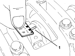
- Clean any residues of gasket from the the cylinder head - engine block matching surfaces.- Place the cylinder head gasket in position. | The gasket should be positioned with the word "TOP" facing upwards. |
- Place the cylinder head in position. | Two mechanics are needed for this operation.- Check that the centering bushes are correctly positioned.Take care to raise the timing chain and the exhaust side camshaft drive pulley. |
1. Tighten the new cylinder head fixing bolts to the recommended torque using the angular tightening tool. | Follow the order shown in the figure for each tightening sequence. |
| Component | Fastening | dia | Value (daNm) | Validity |
|---|
| Cylinder head | Bolt (to be replaced) | M11 x 1.5 | (engine crankcase side) 3.0 + 90° +60° +15° | 2.2 |
| Tool | Description | Function | Validity |
|---|
| 1860942000 | Torque wrench | Tighten bolts to torque plus angle | |
2. Tighten the new bolts securing the cylinder head to the recommended torque.| Component | Fastening | dia | Value (daNm) | Validity |
|---|
| Cylinder head | Timing side bolts (to replace) | M8 X 1.25 | (engine crankcase side) 3.5 | 2.2 |
- Tighten the upper bolt fixing the belt tensioner pad to the recommended torque.| Component | Fastening | dia | Value (daNm) | Validity |
|---|
| Timing fixed chain tensioner pad | Upper bolt | M6 x 1 | (cylinder head side) 0.8 | 2.2 |
- Replace the access plug to the upper belt tensioner bolt in its seat and tighten to the specified torque. | Replace the seal. |
| Component | Fastening | dia | Value (daNm) | Validity |
|---|
| Cap for timing fixed chain tensioner pad upper bolt | - | M22 x 1.5 | 6.5 | 2.2 |
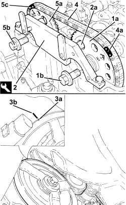
- Remove the band used for fastening the timing chain to the exhaust side camshaft toothed drive pulley.1. Place the intake side camshaft toothed drive pulley (1a) in its housing and secure it with a new bolt (1b) without tightening the bolt.2. Fit the camshaft timing tools. | Turn the intake side camshaft by means of the hexagon until timing tool pin (2a) fits into the hole on the pulley. |
| Tool | Description | Function | Validity |
|---|
| 2000000900 | Template | Camshaft timing adjustment | 2.2 |
3. If necessary, rotate the crankshaft until cylinder no. 4 is at T.D.C. during the explosion stroke; in this condition the reference (3a) on the inner part of the crankshaft pulley should be aligned with the reference (3b) on the timing chain cover. | Turn the crankshaft slowly and steadily (in the direction of engine rotation). |
| Ensure the timing chain is not stuck. |
4. Fit the timing chain on the inlet side camshaft drive pulley. | The light blue mesh (4a) should be in line with the "INT" mark stamped on the inlet side camshaft drive pulley. |
5. Place the exhaust side camshaft toothed drive pulley (5a) in its housing and secure it without tightening the new bolt (5b). | Turn the exhaust side camshaft by means of the hexagon until the pink link (5c) is aligned with the "EXH" mark stamped on the exhaust side toothed timing drive pulley. |
- Move back the camshaft timing tool pin from the intake side camshaft toothed timing drive pulley.
- The following drawing shows the fixed timing chain hydraulic tensioner disassembled. | Replace the seals. |
- Before refitting, the timing chain hydraulic tensioner must be preloaded as described below.1. Position the piston in a vice with protective jaws, holding it by the square end.2. Insert the piston into the tensioner case by pressing and turning as shown in the figure until the pin (2a) fits into the groove (2b).3. Press and simultaneously turn the piston until the pin (3a) fits into the groove (3b).- Insert the assembled piston into the tensioner body.
- Refit the timing chain hydraulic tensioner into its seat and tighten to the specified torque.| Component | Fastening | dia | Value (daNm) | Validity |
|---|
| Timing fixed hydraulic tensioner | - | M27 x 2 | 7.5 | 2.2 |
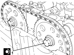
1. Hydraulic tensioner in operating position. | Move the timing chain hydraulic tensioner to operating position by exercising overall pressure by hand on the chain in the area shown in the figure. This puts the chain under tension, which in turn acts on the mobile pad to release the mobile tensioner piston.When the tensioner piston is operated, the operating spring can be heard to click. |
| If the chain remains slack, the tensioner is not in the operating position. |
- Rotate the crankshaft through 720°, then place cylinder no. 4 at T.D.C. during the explosion stroke; in this condition the reference on the inner part of the crankshaft pulley should be aligned with the reference on the timing chain cover. | When the crankshaft is turned, the tensioner piston should follow the chain through its rotation. |
- Check the timing by ensuring that the tool pins are aligned with the holes on the camshaft drive pulleys. | If they do not align, refit the timing chain without treating the coloured links on the chain as TDC reference points. |
- Remove the tool.| Tool | Description | Function | Validity |
|---|
| 2000000900 | Template | Camshaft timing adjustment | 2.2 |
Place the upper timing chain pad in its housing and fasten it tightening the bolts to the recommended torque.| Component | Fastening | dia | Value (daNm) | Validity |
|---|
| Timing upper chain tensioner pad | Bolt (with thread-locking agent) | M6 x 1 | (cylinder head side) 1.0 | 2.2 |
1. Tighten the new camshaft toothed pulley bolts to the specified torque, first tightening the exhaust side pulley bolt. | Turn the hexagonal bolts on the camshafts to provide countertorque. |
| Component | Fastening | dia | Value (daNm) | Validity |
|---|
| Camshaft toothed drive pullies | Bolt (to be replaced) | M12 x 1.75 | (camshaft side) 8.5 + 30° + 15° | 2.2 |
- Place a new gasket back in position.1. Place the exhaust manifold (1a) in its housing and secure it by tightening the new nuts (1b) to the recommended torque.| Component | Fastening | dia | Value (daNm) | Validity |
|---|
| Exhaust manifold with catalytic converter | Nut (to replace) | - | (cylinder head side) 2.0 | 1.82.2 |
1. Place the heat shield (1a) in its housing and secure it using the bolts (1b).2. Position the front Lambda sensor in its housing and tighten it to the recommended torque.| Component | Fastening | dia | Value (daNm) | Validity |
|---|
| Front Lambda sensor to catalytic converter | - (with special black grease) | M18 x 1.5 | (exhaust manifold with catalytic converter side) 4.0 | 2.2 |
- Place the ignition coil module in its housing and secure it tightening the bolts to the recommended torque.| Component | Fastening | dia | Value (daNm) | Validity |
|---|
| Ignition coil module | Bolt | M6 x 1 | (tappet cover side) 0.9 | 2.2 |
- Connect the electrical connection to the ignition coil module.