194000322 - 1056B90 SYSTEM CABLE LOOM - R.R.
| Description | Connector | |
|---|---|---|
| - | Battery | See A001 BATTERY |


| Description | Connector | |
|---|---|---|
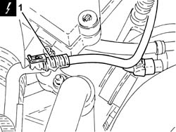
| 1 | Lambda sensor on catalyzer | See K017 LAMBDA SENSOR ON CATALYZER |
| Description | Connector | |
|---|---|---|
| 2 | Lambda sensor on catalyzer - 2 | See K018 LAMBDA SENSOR ON CATALYZER - 2 |

| Description | Connector | |
|---|---|---|
| 1 | Air flow meter | See K041 AIR FLOW METER |

| Description | Connector | |
|---|---|---|
| 1 | Fuel vapour recovery solenoid valve | See L010 FUEL VAPOUR RECOVERY SOLENOID VALVE |
| Description | Connector | |
|---|---|---|
| 2 | 4 stage pressure switch | See K010 4 STAGE PRESSURE SWITCH |
| Description | Connector | |
|---|---|---|
| 1 | Engine management control unit | See M010 ENGINE MANAGEMENT CONTROL UNIT |
| Description | Connector | |
|---|---|---|
| 2 | Engine management control unit | See M010 ENGINE MANAGEMENT CONTROL UNIT |

| Description | Connector | |
|---|---|---|
| 1 | Engine cables/engine services cable coupling | See D029 ENGINE CABLES/ENGINE SERVICES CABLE COUPLING |
| Description | Connector | |
|---|---|---|
| 2 | Integrated throttle casing actuator | See N075 INTEGRATED THROTTLE CASING ACTUATOR |
| Description | Connector | |
|---|---|---|
| 3 | Absolute pressure sensor | See K048 ABSOLUTE PRESSURE SENSOR |

| Description | Connector | |
|---|---|---|
| 1 | Injector | See N070 INJECTOR |

| Description | Connector | |
|---|---|---|
| 1 | Ignition coil | See A030 IGNITION COIL |

| Description | Connector | |
|---|---|---|
| 1 | Interference filter | See P087 NOISE FILTER |

| Description | Connector | |
|---|---|---|
| 1 | Engine coolant temperature sensor/sender unit | See K036 ENGINE COOLANT TEMPERATURE SENSOR/SENDER UNIT |

| Description | Connector | |
|---|---|---|
| 1 | Rpm sensor | See K046 RPM SENSOR |
| Description | Connector | |
|---|---|---|
| 2 | Insufficient engine oil pressure sensor (switch) | See K030 INSUFFICIENT ENGINE OIL PRESSURE SENSOR |

| Description | Connector | |
|---|---|---|
| 1 | Detonation sensor | See K050 DETONATION SENSOR |
| Description | Connector | |
|---|---|---|
| 2 | Earth on engine | See C040 EARTH ON ENGINE |


| Component | Fastening | dia | Value (daNm) | Validity |
|---|---|---|---|---|
| Injection/ignition system control unit | Bolt | M6 x 1 | (air chamber side) 0.9 | 2.2 |