194001924 - INTRODUCTION - ELECTRICAL CIRCUITS FOR INSTRUMENTS/GAUGES
MINI F.L.Ore.N.C.E. ELECTRICAL AND ELECTRONIC SYSTEM
General specifications
In conventional electrical systems, functions are activated with the aid of dedicated point-to-point linesThe increase in the number of electrical/electronic devices on board cars has given rise to heavier and more complex connections. This is partly due to the complexity of the functions implemented in the burgeoning number of electronic units - which also need to exchange data continually: all this makes new electrical systems more difficult to install and increases the complexity of fault diagnosis.Many problems have been overcome and new electrical systems have been optimised compared to conventional systems by using a network form of connection. This provides a more effective means of managing communication on the board the car and of transferring data between the various subsystems. Information is distributed via serial pathways (buses) that may take the form of: individual wires, twisted wire pairs or even optical fibres. Let us now take a look at the move from traditional systems to those known as multiplexing systems.Conventional solutionThe four control units illustrated below require a number (N) of wires for each input/output data item in order to perform their function. This multiplied the amount of cable required to the point that systems are made more complex (design and manufacture) and more voluminous (weight, bulk, cost). Some 40 kg of wiring looms are required that stretch for more than 2 km - and this figure could double every 10 years because even now a car could be equipped wiht 20 to 40 electronic control units (ECUs).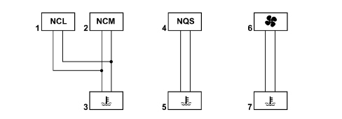


Mini F.L.Ore.N.C.E. SYSTEM STRUCTURE
General specifications
The Mini F.L.Ore.N.C.E. structure for this model manages some of the vehicle''s electrical equipment, controlling the bodywork functions directly (control of access, visibility, on board information, comfort, etc.).To improve the system, the structure follows the regional topological approach: each control unit (electronic or electromechanical) is located in a centre of gravity position in relation to the functions managed.This allows the power and signal distribution system to be minimised. This is also made possible through extensive use of serial communication networks that allow us to overcome problems of space-saving, reliability, weight and cost.The structure consists of three CAN communication networks which connect nodes belonging to the three different areas (vehicle dynamic control, on board information and bodywork functions) and a certain number of complementary serial lines.Power is distributed via the junction units and/or fuse boxes connected to control elements (relays and static actuators) to ensure maximum electrical protection and minimum complexity of the wiring. All wiring looms have been made modular by changing the way functions are distributed inside the connectors and replacing welds with short-circuiting joints. The structure of the wiring has been designed to simplify the fitting through the reduction in the number of sections, the reduction in lengths and the elimination of critical crossovers and has also been designed to encourage the production of all cable looms in a modular manner (through the composition of subassemblies) with the aim of producing the most simple in line sequencing of the wiring on the Fiat Auto production lines.The possibility of using the most up to date automatic wiring construction equipment has also been taken into account.The system (e.g.: door wiring, dashboard wiring) can potentially be adapted for automatic wiring production systems.The architecture developed is compatible with various user interface solutions (control arrangement, information allocation and display method).The electrical protection (fuses) and the relays are grouped together in the power distribution junction units located in the engine compartment and the dashboard. These junction units also act as connections for the various wiring and electrical distribution.Modular systemWiringTo allow the construction for subassemblies (electrical functions) and to facilitate the possible automatic production, all welding (splice) and couplings with minted terminals has been avoided; even if this restricts the advantages of automatic production, soldering or minting can be used for coupligns that do not interconnect different assemblies. To produce a minimum number of wiring families, each circuit has a section coupling that should maintain the same position inside the coupling, irrespective of the trim level; the position and the type of the coupling on the vehicle should also not depend on the trim level (high or low).ComponentsTo safeguard the modular nature of the wiring the inlets/outlets for each junction unit should not differ according to the trim level/engine type, the position of the connector or the cable/terminal/connector interface.System structure
The electrical/electronic system has the following classification:- Fuse/relay box;- Electronic compnents;- User control modules;- Electrical/electronic interfaces with non Fiat Auto systems.Fuse/relay boxThe components for this model are listed in the table:| Identification code | Description |
|---|---|
| CBA | Battery control unit |
| CPL | Dashboard control unit |
| CVB | Boot comparment control unit |
| CVM | Engine compartment junction unit |
| Identification code | Description |
|---|---|
| CAV | Volumetric Alarm Control Unit |
| CDC | CD-Changer |
| CSA | Anti-theft Alarm Control Unit |
| DSP | Hi-fi / Bose audio amplifier |
| NBC | Body Computer Node |
| NBS | Steering Lock Node |
| NIT | Info Telematic Node |
| NPG | Driver''s door node |
| NPP | Passenger Door Node |
| NQS | Instrument Panel Node |
| NRR | Radio Receiver Node |
| NSP | Parking Sensor Node |
| NVB | Luggage compartment node |
| NVO | Steering wheel Node |
| NTR | Teg Reader Node |
| Identification code | Description |
|---|---|
| CAP | Electric Window Controls on passenger front/rear Doors |
| CEM | Hazard warning lights control |
| CLA | Brake Lights Control |
| PCS | Left Control Panel |
| DEV | Steering column switch unit control module |
| IFR | Switch on Clutch |
| PCP | Control Panel on driver''s front Door |
| PCT | Control Panel on Tunnel |
| An interface refers to the method of exchanging information with the vehicle''s electrical system (CAN, serial, discrete). |
| Identification code | Description |
|---|---|
| CPD | Right Headlamp Control Unit |
| CPR | Heater Plugs Control Unit |
| CPS | Left Headlamp Control Unit |
| CRS | Additional Heater Control Unit |
| CSP | Rain/dusk Sensor Control Unit |
| CTA | Sun Roof Control Unit |
| NAB | Air Bag Node |
| NAG | Driver Position Node |
| NAP | Passenger Position Node |
| NAS | Steering Angle sensor Node |
| NCA | Automatic Transmission Node |
| NCL | Climate Control Node |
| NCM | Engine Management Node |
| NFR | Braking System Node |
| NGE | Electrohydraulic Steering Node |
| NSC | Gearbox Selector Node |
| NYL | Lateral Yaw sensor Node (slewing sensor) |
Structure of the networks
The most extensive structure consists of:-2 CAN communication NETWORKS which connect NODES belonging to two different areas: one for the dynamic control of the vehicle and one for the so-called "bodywork" functions;- a W SERIAL LINE for immobilizer recovery;- different K SERIAL LINES for the fault diagnosis of several NODES/CONTROL UNITS;- a serial line known as A - BUS.| NODES are all the electrical/electronic devices and control units that contain a specific interface (NETWORK INTERFACE) that allow data, information and signals travelling via the CANs to be transmitted and received. |
| Identification code | Description |
|---|---|
| CAV | Volumetric Alarm Control Unit |
| CDC | CD-Changer |
| CPL | Dashboard control unit |
| CPD | Right Headlamp Control Unit |
| ... DATA ERROR - CROPPED TEXT | Ошибка данных - Текст обрезан ... |
|---|