194001925 - 5505A MULTI-FUNCTION COMPONENTS
BODY COMPUTER NODE
Specifications
The Body Computer Node (NBC) is an electronic component connected to the vehicle serial networks which manages the basic functions of the Mini F.L.Ore.N.C.E structure (interior/exterior lighting, immobilizer, fault diagnosis, heated rear windscreen, door locking, alarm, fuel level) and houses the gateway between the B-CAN and the C-CAN.The NBC also carries out interconnection functions between the dashboard, front and rear wiring and is connected to the Dashboard Control Unit (CPL) by means of a connector at the front.There is also a fixed EOBD connector at the front capable of carrying out the fault diagnosis via the K line for the Engine Management Node and the systems not connected to the B-CAN line (e.g. the air bag) and via the B-CAN line for the nodes connected to it. There is a possible assembly programme for the latter.General functions of the body computer node
To sum up, the NBC carries out the following functions:- Receives and transmits information on the B-CAN (e.g.: diagnosis, warning lights, controls, data);- Receives and transmits information on the C-CAN;- Houses the gateway for communication between the C-CAN and B-CAN;- Is connected to the dashboard, front and rear wiring;- Allows interface for fault diagnosis (EOBD);- Low consumption supply mode management (Logistic Mode);- Is connected to the CPL to take supplies/signals and operate relays.The following functions are included:- management of the courtesy lights with a timer and dimmer function;- management of the on/off outputs at the relays: headlamp washer pump, main beam headlamps, fog lights, dipped headlamps, rear windscreen and services,- on/off management of left/right direction indicators and hazard warning lights;- on/off output management directly at loads and light check function: front and rear side lights (left and right), front, rear and side direction indicators (left and right), number plate lights (left and right), brake lights (left and right), rear fog lamps (left and right);- management of the on/off outputs at the loads: hazard warning LED, etc.;- acquisition and repetition of vehicle speed signal;- management of the driver for the ideogram lights;- management of the driver for SBMT (switching off loads with ignition OFF);- recovery serial line (W) management to engine management control unit (immobilizer);management of serial line (A-BUS) to rain/dusk sensor, steering column switch unit, volumetric alarm control unit and tyre pressure control unit;- entire system master: management of slave nodes in its direct jurisdiction and monitoring by other master nodes, monitoring and management of protocol errors, timer control;- entire system fault diagnosis: collection of diagnostic information, management of fault diagnosis through EXAMINER.;- acquisition of on/off signals: control of dipped headlamps, control of main beam headlamps, control of boot lock opening, control of boot lock locking, handbrake control, hazard warning lights control, left and right rear fog lamps control, fog lights relay control, left direction indicators control, right direction indicators control, parking lights control, side lights control, city control, steering column switch unit auto control, headlamp washer control, FIS control, boot button, bonnet button, front brake pad wear, brake fluid level, reverse gear engaged;- acquisition of analogue signals: fuel level, alternator voltage (D+), battery voltage;- recognition of brake lights fuse status, centre courtesy light control, left and right spot lights control, brake lights controls, acquisition of signals for lock sensors from doors;- preparation for possible inclusion of new electric functions.Refer to the pin out described later on for the description of further functions in detail.
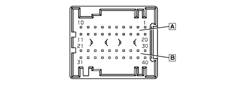
Body computer connections
The Body Computer connections are illustrated in the diagram.
| Pin | Function |
|---|---|
| 1 | Reverse gear engagement positive signal for electrochromic mirror/rearscreen wiper |
| 2 | Left side direction indicator control output |
| 3 | N.C. |
| 4 | N.C. |
| 5 | N.C. |
| 6 | N.C. |
| 7 | Speedometer signal input (VSO) from NFR |
| 8 | Fog lights relay negative signal |
| 9 | Main beam headlamps relay negative signal |
| 10 | INT for CPS, CPD |
| 11 | +30 battery power supply (CSA, NAS, CAV, EOBD diagnostic socket, courtesy lights) |
| 12 | N.C. |
| 13 | Positive input from steering column switch unit for headlamp washer control/wish-wash signal |
| 14 | Headlamp washer relay negative signal |
| 15 | N.C. |
| 16 | NFR node K line |
| 17 | N.C. |
| 18 | Negative signal from switch signalling insufficient brake fluid level (NA) |
| 19 | Alternator D+ signal |
| 20 | K line for NCM and NCA nodes diagnosis |
| 21 | N.C. |
| 22 | Right side direction indicator control output |
| 23 | Negative signal from left front brake pad wear sensor |
| 24 | Negative signal from NC switch signalling bonnet open |
| 25 | A-bus serial line for CPP, CSA and DEV |
| 26 | B-CAN A |
| 27 | B-CAN B |
| 28 | Repetition of speedometer signal (VSO) for CPS |
| 29 | IN/OUT recovery serial for NCM (immobilizer) - W line |
| 30 | Right front side light operation output |
| 31 | N.C. |
| 32 | C-CAN L (preparation) |
| 33 | C-CAN H (preparation) |
| 34 | +30 for CSA |
| 35 | K line for CPS, CPD, NGE |
| 36 | C-CAN L to NYL |
| 37 | C-CAN H to NYL |
| 38 | Left front direction indicator control output |
| 39 | Right front direction indicator control output |
| 40 | Left front side light operation output |
| Pin | Function |
|---|---|
| 1 | K line for NFR |
| 2 | Not available |
| 3 | K line for Air Bag (N.C.) |
| 4 | Power earth |
| 5 | Signal earth |
| 6 | B-CAN B |
| 7 | K line for NCM and NCA nodes diagnosis |
| 8 | Not available |
| 9 | K line for dashboard zone (preparation) |
| 10 | Not available |
| 11 | Not used |
| 12 | K line for front zone (CPS, CPD, CRS, NGE) |
| 13 | K line for rear zone (CPP) |
| 14 | B-CAN A |
| 15 | Not available |
| 16 | +30 battery power supply |

| Pin | Function |
|---|---|
| 1 | N.C. |
| 2 | N.C. |
| 3 | Right rear direction indicator control output |
| 4 | Fuel level input |
| 5 | Left rear side light operation output |
| 6 | Right rear side light operation output |
| 7 | A-bus serial line for CAV and CSP |
| 8 | Negative signal from NA switch signalling front driver''s door open |
| 9 | Left/right no. plate light control output |
| 10 | Sun roof remote control/enabling negative signal |
| 11 | Repetition of speedometer signal (VSO) for CTA |
| 12 | Left rear direction indicator control output |
| 13 | N.C. |
| 14 | Negative signal from switch signalling handbrake applied (NA) |
| 15 | Fuel level input (negative) |
| 16 | Negative signal from NA switch signalling left rear door open |
| 17 | Inertia switch signal negative input (F.I.S.) |
| 18 | K line for CPP |
| 19 | N.C. |
| 20 | Right rear fog lamp control signal |
| 21 | Centre front courtesy light timed/dimmed negative control (20W max) |
| 22 | Right brake light control signal |
| 23 | +30 SBMT for luggage compartment courtesy light (20W max) |
| 24 | Negative signal from NA switch signalling boot not properly shut |
| 25 | Negative signal from NA switch signalling passenger front door open |
| 26 | Negative signal from NA switch signalling right rear door open |
| 27 | +30 battery for front/rer courtesy lights |
| 28 | Analogue signal for left/right spot light in centre front courtesy light |
| 29 | N.C. |
| 30 | Timed negative control for left spot light in centre front courtesy light (10W max) |
| 31 | Left rear fog lamp control signal |
| 32 | Left brake light control signal |
| 33 | +30 SBMT for courtesy light under driver/passenger sun visor |
| 34 | N.C. |
| 35 | Negative signal for opening switch on boot handle |
| 36 | Negative signal from NA switch signalling boot open |
| 37 | Timed negative control for right spot light in centre front courtesy light (10W max) |
| 38 | N.C. |
| 39 | +30 battery for CAV |
| 40 | Activation of lighting on constantly with side lights on for cigar lighter, electrochromic mirror, current socket |

| Pin | Function |
|---|---|
| 1 | +30 battery for boot unlocking geared motor |
| 2 | Left/right brake lights positive control signal from CPL |
| 3 | Positive signal for switching on reversing light from CPL |
| 4 | Not available |
| 5 | B-CAN B for CPL |
| 6 | Negative signal controlling heated rear windscreen relay coil |
| 7 | B-CAN A for CPL |
| 8 | Negative signal controlling dipped headlamps relay coil |
| 9 | INT from NBS |
| 10 | N.C. |
| 11 | Boot release geared motor positive control |
| 12 | N.C. |
| ... DATA ERROR - CROPPED TEXT | Ошибка данных - Текст обрезан ... |
|---|