194001940 - INTRODUCTION - BRAKES
SPECIFICATIONS
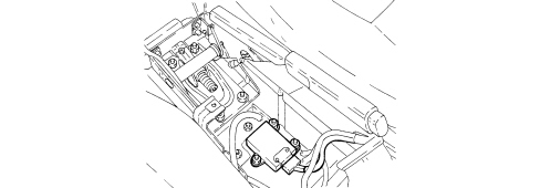
The braking system is the power assisted hydraulic type, comprising two crossover, independent ciruits (each circuit acting on one front wheel and the diagonally opposite rear wheel) to ensure braking and stability even if one of the circuits fails.The ABS + ESP versions include the following systems:- ABS: anti-lock brakes;- EBD: electronic brakeforce distribution between the front and rear wheels;- ASR: traction control via management of the brakes and engine control unit;- MSR: engine brake control by means of engine control unit management;- ESP: vehicle electronic stability control;- HBA: automatic increase in braking pressure during emergency braking;- Hill Holder: assisted hill start system that keeps the vehicle braked while parked on slopes and automatically releases the brakes when the driver wishes to set off.The system consists of the following components:- 4 magnetic rings incorporated in the wheel bearings;- 4 wheel speed sensors fitted in special housings in the front and rear dampers;- 1 steering angle sensor built into the steering column switch unit (versions with ESP only);- 1 lateral acceleration, longitudinal or slewing sensor (or node) housed in a single device fitted on the tunnel between the front seats;- 1 electro-hydraulic unit fitted on the special support in the engine compartment;- 1 ON/OFF button in the dashboard for the ASR anti-slip function (versions with ESP only);- 1 clutch pedal position sensor;- reversing switch fitted on the gearbox.BRAKING SYSTEM COMPONENTS
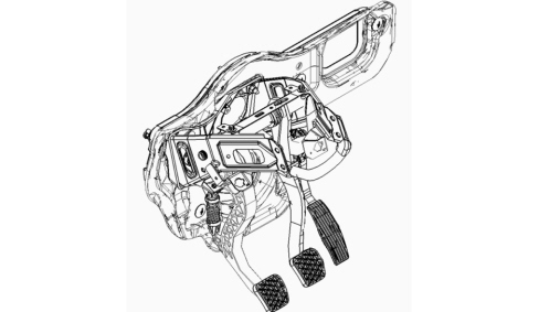
Pedal unit
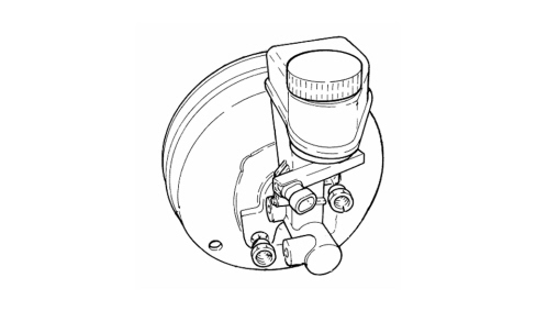
Brake servo
Caliper-brake disc
On account of differences in weight and power for the various engine types, the braking system has suitable size discs and calipers as described in the Technical Data section.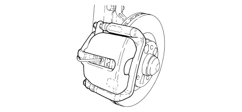
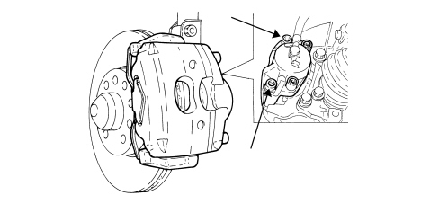
| Teves calipers cannot, under any circumstances, be dismantled and/or the bolts (shown in the diagram) that join the two parts undone !This operation can only be done in the factory using special gauges. Dismantling and then reassembling the two parts of the caliper will result in non alignments that would have a serious adverse affect on safety when braking. |
ABS SYSTEM
This vehicle is fitted with ABS TRW EBC430 New Generation anti-lock brakes with 4 active sensors and 4 channels with built in electronic brakeforce distribution (EBD).The active safety features are:- ensuring the best possible braking for each wheel close to locking compatible with the grip available;- safeguarding the full control of the vehicle in extreme conditions close to the wheels locking guaranteeing excellent handling;- quickest possible reponse;- capacity to automatically recognize the most diverse grip conditions (slipping, poor grip, good grip, unmade road).Electronic control unit
The control unit processes the following signals:- steering wheel rotation angle- lateral acceleration and slewing- engine operating conditions:- wheel rpm- hydraulic braking system pressure.From the figures received it processes the data using special algorithms in the electronic control unit software to obtain the figures for the dynamic control of the vehicle:- longitudinal and transverse sliding between the wheels and the road surface- axle drift.Using these figures the system interprets the effective dynamics of the vehicle; having identified all the critical conditions due to environmental factors (e.g. surface with poor grip) or any errors made by the user (e.g. panic situations) and with subsequent intervention on the brakes and the drive torque, the vehicle is restored to good driving conditions.The system interfaces with:- NCM for drive torque adjustment via the C-CAN line;- control panel via a serial line for warning light control.Electrohydraulic unit
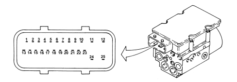
The operation of the electrohydraulic unit is similar in the "ABS only" and ABS + ESP systems.The operation of the unit with ESP as well is described below for reasons of simplicity.SignalsInput signals:- wheel speed sensors (from direct line);- brake pedal three stage switch (from direct line);- ASR off button (from direct line);- engine management control unit (from C-CAN line);- throttle angle position (from C-CAN line);- control panel;- warning light status signal (from dedicated serial line);- slewing sensor (longitudinal) (from C-CAN line);- lateral acceleration sensor (from C-CAN line);- steering angle/steering wheel rotation sensor (from C-CAN line);- hydraulic system pressure sensor (from direct line);- acceleration sensor (from C-CAN line);Output signals:- brake pressure modulation control;- ignition advance reduction control (from C-CAN line);- engine power management control (from C-CAN line);- injection time management control (from C-CAN line);- engine power management control (from C-CAN line);- VSO signal (vehicle speed);- ESP-HH-ASR-ABS-EBD warning lights in panel control (from dedicated serial line);- ASR LED off.The electronic control unit carries out the following functions:- acquiring the data coming from the sensors;- memorises the control parameters defined during the vehicle P.D.I.- memorises the control software- processes the data acquired- controls the braking process- detecting faults in the braking system components;- memorizes the fault codes and activates the ABS/EBD/ASR/HH warning lights;- transmits and receives data via the diagnostic connector- conversing with the engine management control unit- controls the ASR/HBA/ESP/HH functions;- transmitting and receiving data via the C-CAN line.Pin out for abs control unit with esp
Wheel rpm sensors
The wheel rpm sensors are the active type and, like the passive sensors used on previous ABS versions, they have the function of detecting the speed at the wheels. The basic feature of active sensors consists in the fact that the signal is processed directly by the sensor instead of sending a sinusoidal wave to the ABS control unit.The main advantages are:- capacity of reading speed signals close to zero (passive sensors do not read speeds below 2.75 km/h);- less sensitivity to outside interference caused by electromagnetic fields present in towns or areas wih high technological and industrial density.Thanks to the possibility of detecting very low speeds, the active sensors improve the precision of the on board navigation systems.Steering angle sensor (sas) and steering angle node (nas)
The steering angle sensor has the task of measuring the steering wheel turns and the rotation speed and of making them available to the electric steering node (NGE).The SAS is present on versions equipped with ABS only and is supplied together with the electrohydraulic steering assembly.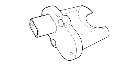
| The steering angle node does not have to be dismantled, under any circumstances, from the steering column switch unit and if it is being replaced it should be reset in relation to the position of the steering wheel using the Examiner. |
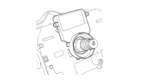
Lateral acceleration/yaw sensor (nyl)
EBD FUNCTION
The inclusion of the EBD electronic brakeforce distribution device in the ABS ensures optimum distribution of the brakeforce compared with old mechanical systems with valves and load proportioning valves: the system is based on measuring the slip of the front and rear wheels and regulates the braking force to ensure that the rear slip is always less than the front slip.Based on the actual grip conditions, the system is capable of automatically adjusting any increases in rear pressure due to variations in the vehicle load conditions, variations in the road gradient and variations in the efficiency of the friction material.ESP SYSTEM
Description
The E.S.P. in other words Electronic Stability Program is an active safety system for the control of the vehicle during dynamic manoeuvres that intervenes in emergency conditions. The Electronic Stability Program acts on the braking system and/or on the supply system to guarantee the stability of the vehicle when the special sensor and steering angle measurement signal that there is a centrifugal force that could adversely affect safety whilst driving or in realignment. The ESP reacts quickly to both oversteer and understeer, returning the vehicle to a stable condition and allowing the driver to keep full control.It is definitely true that this system makes it possible to maintain the same trajectory in poor grip conditions at a higher speed without losing control of the vehicle; however, the resulting improved safety should not induce the customer to alter their driving behaviour which should be appropriate for the actual road surface and traffic conditions.The ESP system switches on automatically when the vehicle is started up and cannot be switched off by the user; the button in the PCC (centre control console) only switches off the ASR function and only when advisable. If the ASR is excluded, the following functions remain activated:ABS/EBD;TC up to a speed of 40 km/h;ESP, HBA, Hill Holder.This system continuously monitors the state of the vehicle (lateral acceleration, longitudinal and angular speed, grip on the ground) and the driver settings (steering wheel angle) and, if it feels that the vehicle is close to an unstable condition (skidding, understeer, oversteer), it corrects the drive torque and applies suitable differentiated braking action at each of the four wheels.Control of the direction takes place by exploiting the longitudinal grip of the tyre: the different braking on the two sides of the vehicle produces a straightening torque (slewing control). which stabilizes the vehicle.Auxiliary driving functions
Hill holderThe Hill Holder system is not a safety feature but provides comfort and is added to the ABS software.The Hill Holder system is designed to assist the driver when setting off on an incline. In effect the Hill Holder system is capable of automatically providing sufficient braking torque to keep the vehicle stationary until the clutch is fully released and the engine toruqe is sufficient to start the vehicle comfortably.Two situations in which the system is extremely useful are illustrated below.The Hill Holder system is automatically activated when the brake pedal is pressed in conjunction with the following conditions:- vehicle speed equal to zero, gradient more than 4-5% and clutch pedal pressed.The moment the brake pedal is released, with all the other conditions being equal, the Hill Holder keeps the braking system pressurized for 1.5 seconds to allow the driver to move their foot from the brake pedal to the accelerator pedal without the vehicle slipping backwards and without using the parking brake.Once the accelerator is pressed, the Hill Holder continues to keep the vehicle still for a further 15 seconds or until the engine torque is sufficient to start the vehicle.The time indicated (of 1.5+10 secs) is the maximum time that the control unit varies (obviously reduces it) if the succession of movements (brake pedal/acceleration/sufficient torque) by the driver is quicker.Conversely, if the driver does not press the accelerator within 1.5 seconds of releasing the brake pedal or the necessary torque is not reached within the additional 15 seconds, the Hill Holder will gradually remove the pressure from the hydraulic circuit.The Hill Holder switches off in poor grip conditions. This is because when stopped on an icy hill, if the Hill Holder keeps all the wheels locked, the vehicle will slip backwards (this is an extreme condition).A slipping recognition test has been designed for these extreme conditions and it is implemented when the ABS or ASR is activated or one of the wheels locks just prior to the engagement of the Hill Holder.During the test stage the control unit (using the ABS parameters) defines which wheel is the m| ... DATA ERROR - CROPPED TEXT | Ошибка данных - Текст обрезан ... |
|---|